
CRT Television Oscilloscope
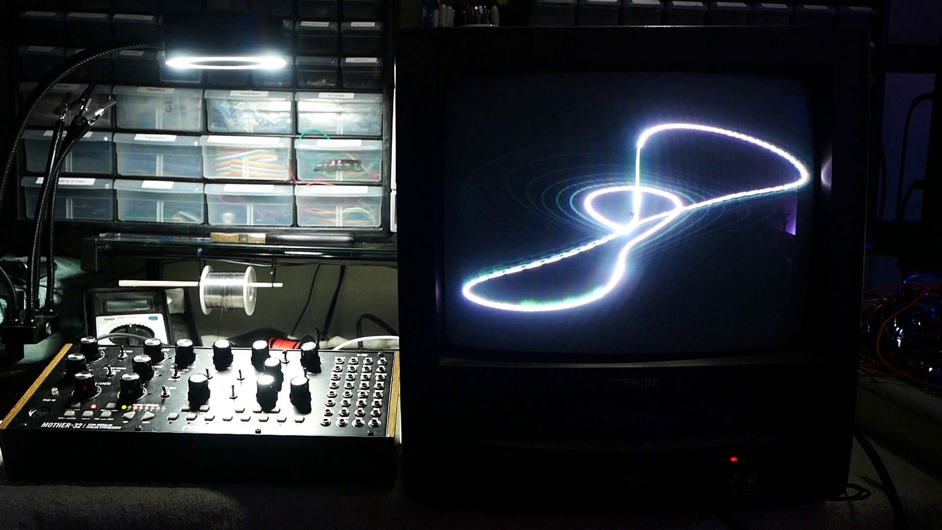
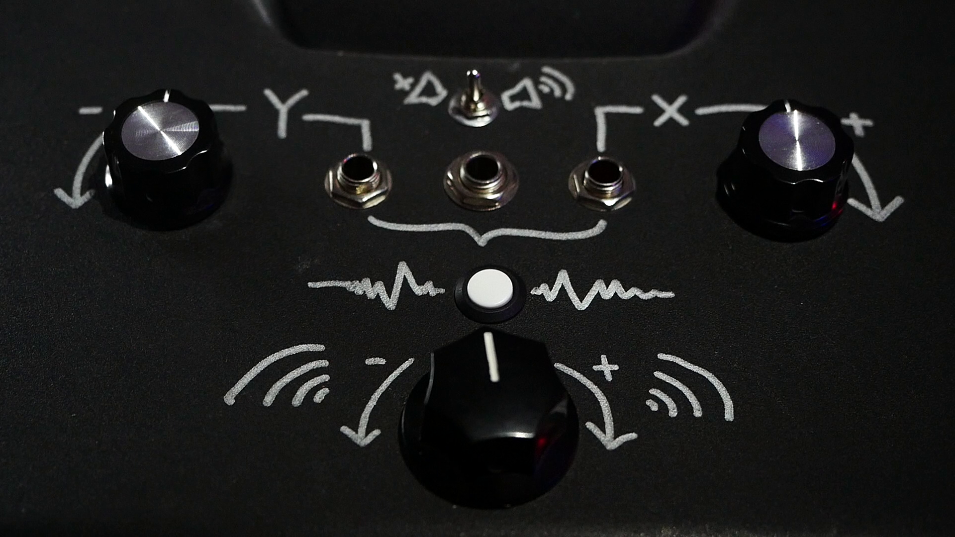
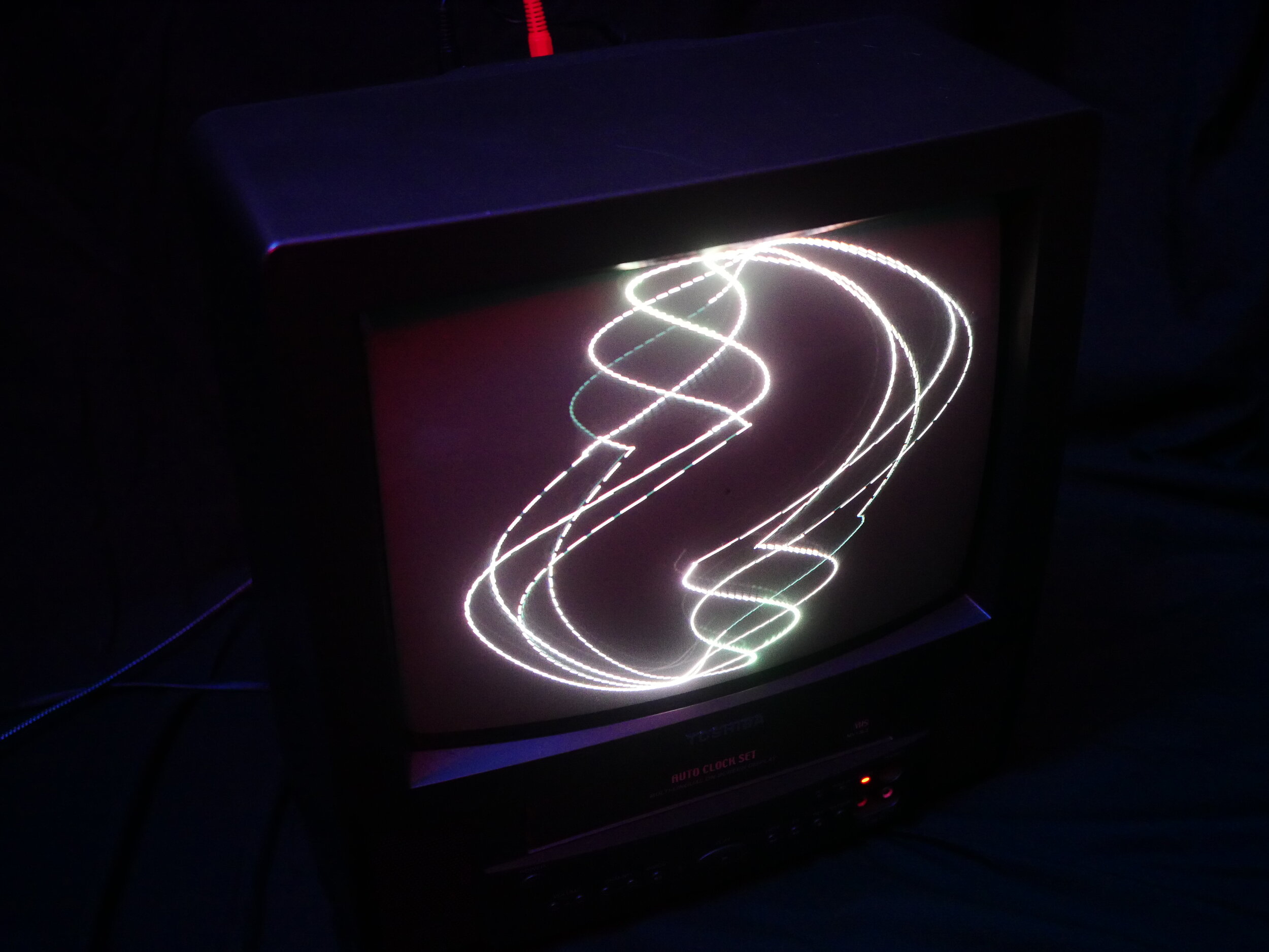
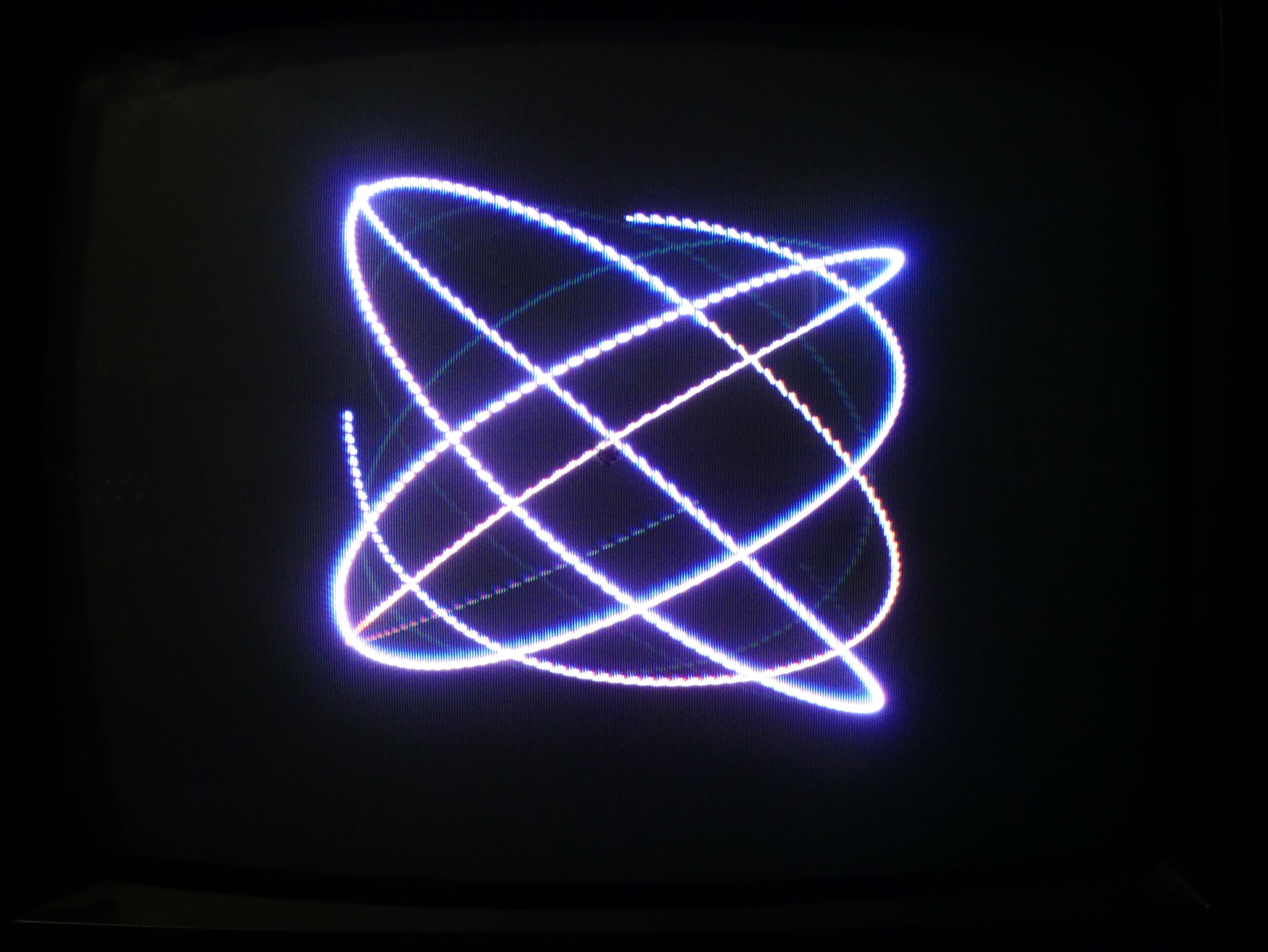
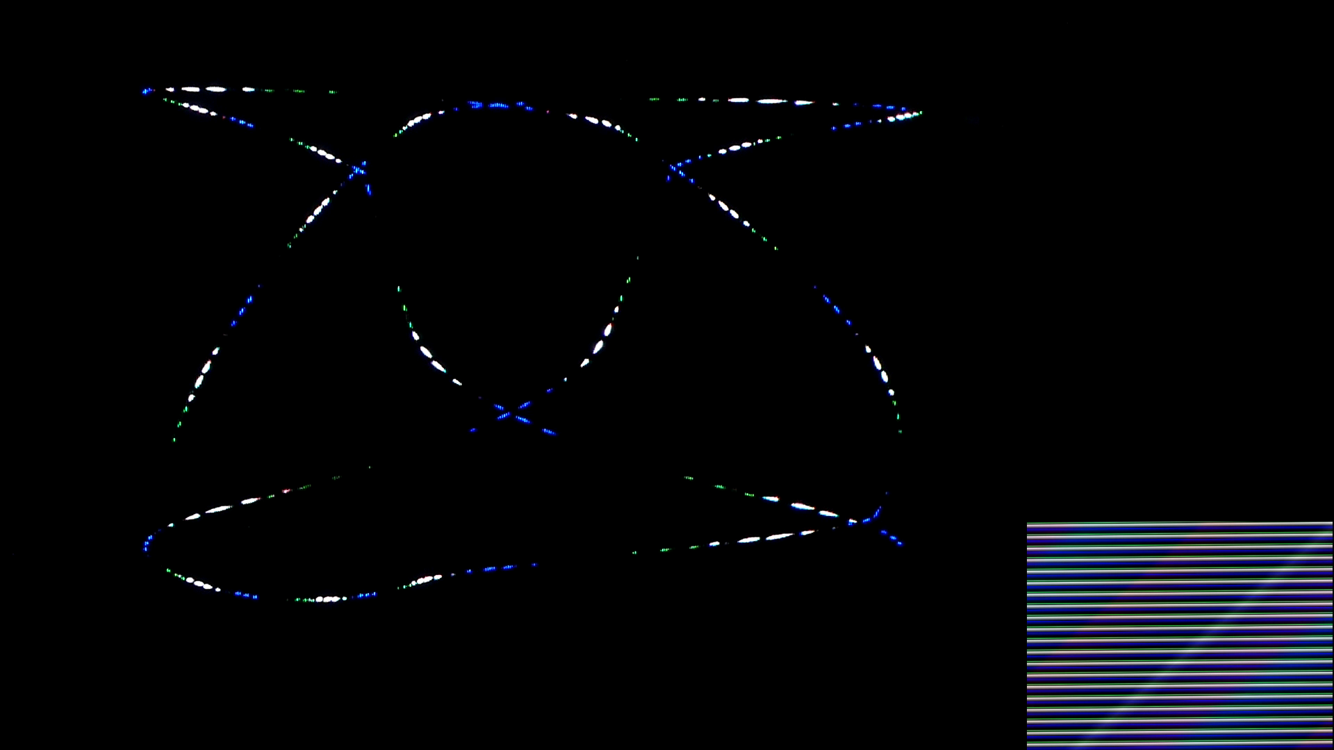
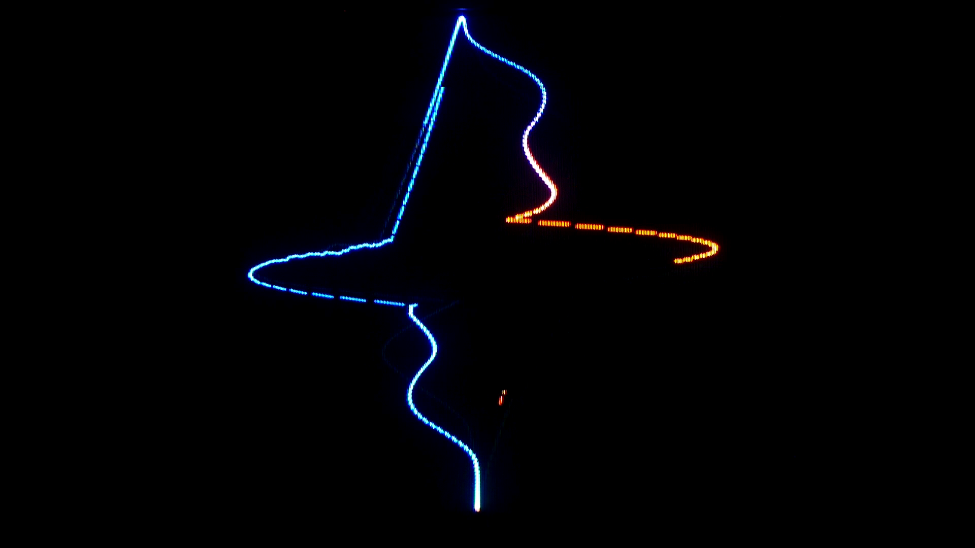
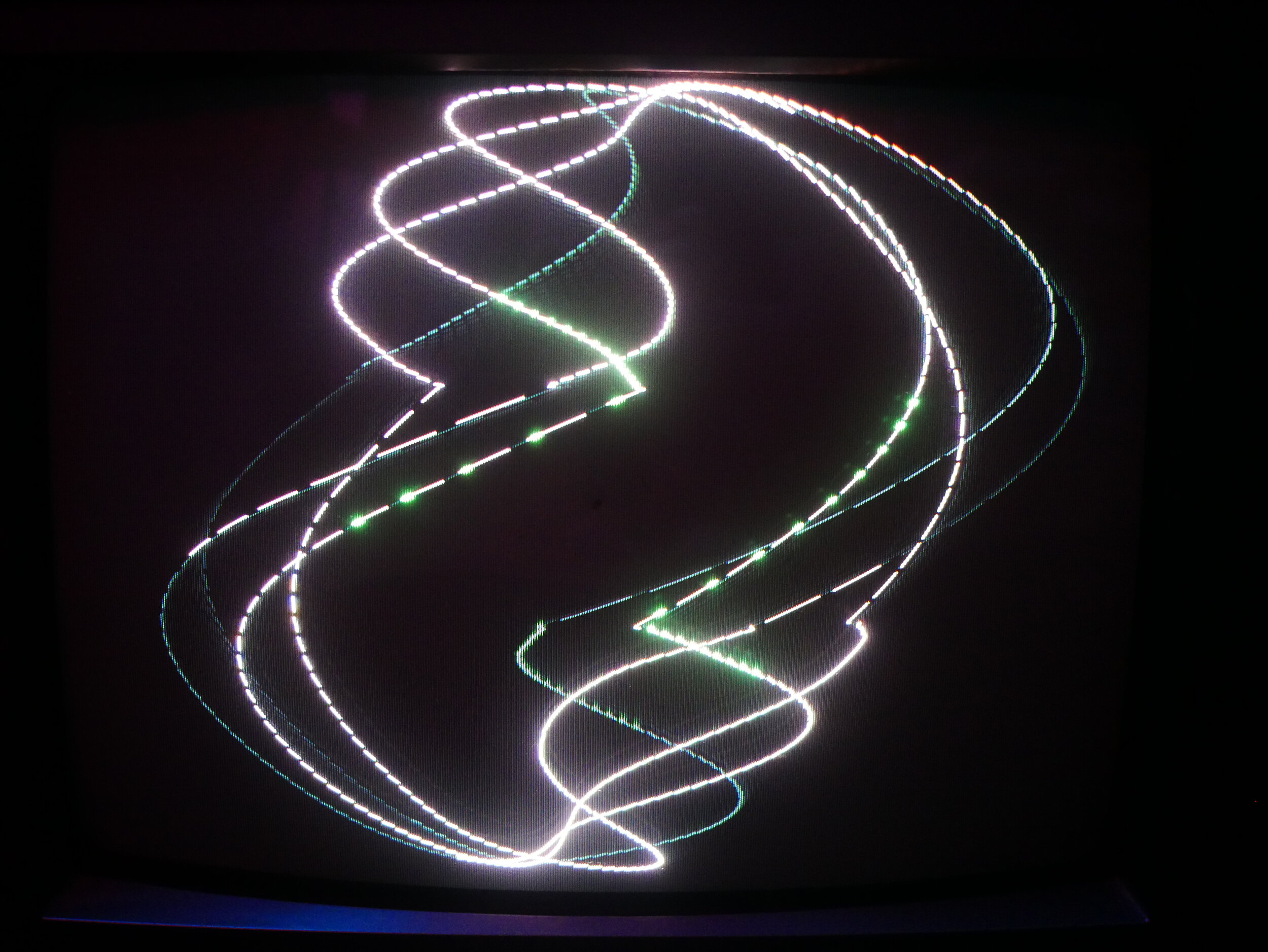
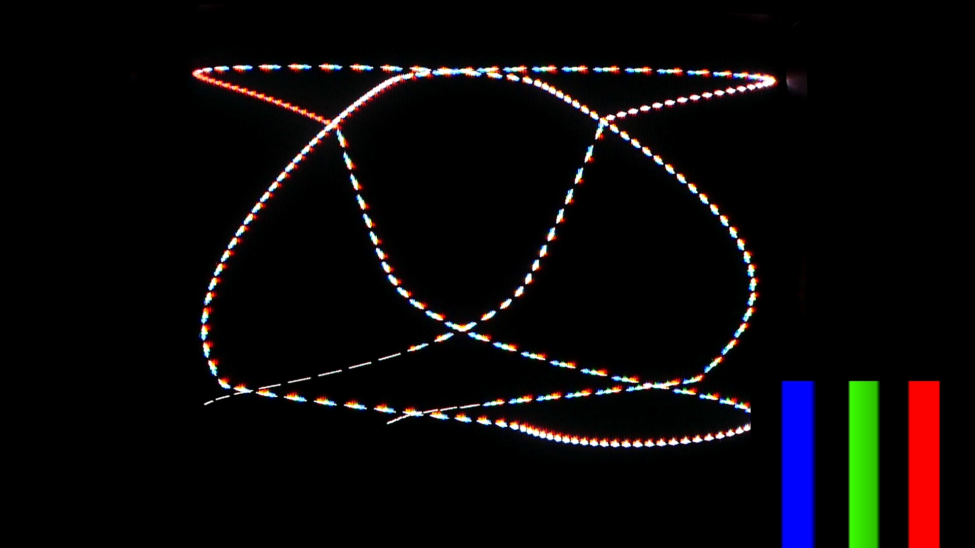
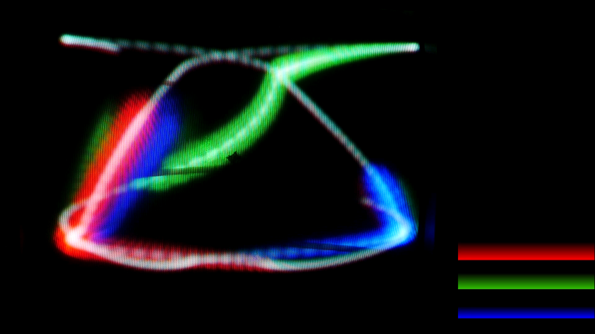
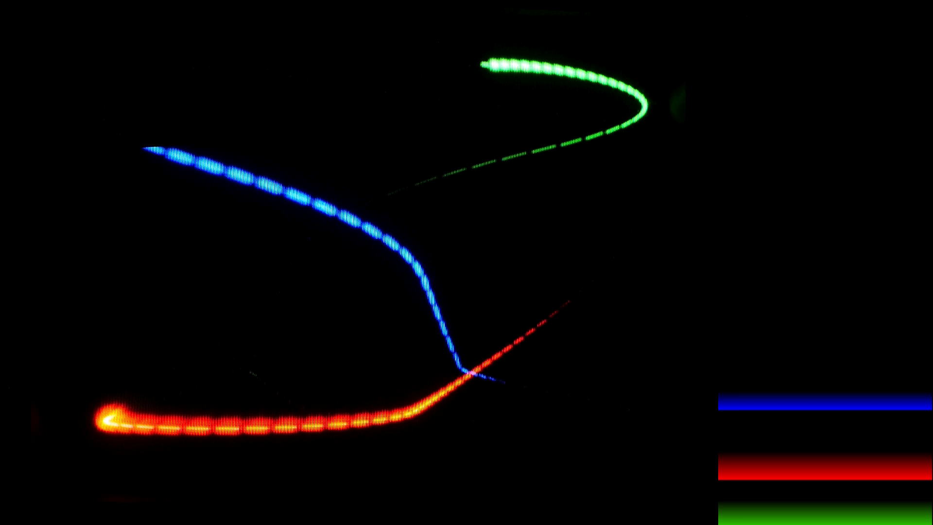
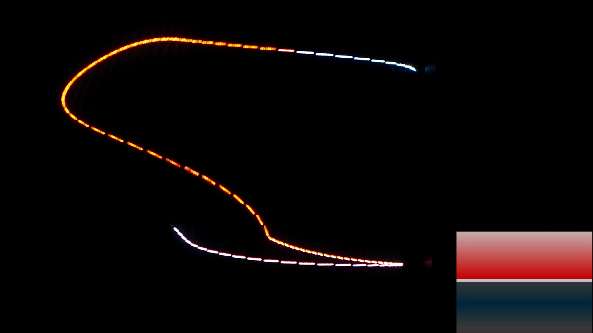
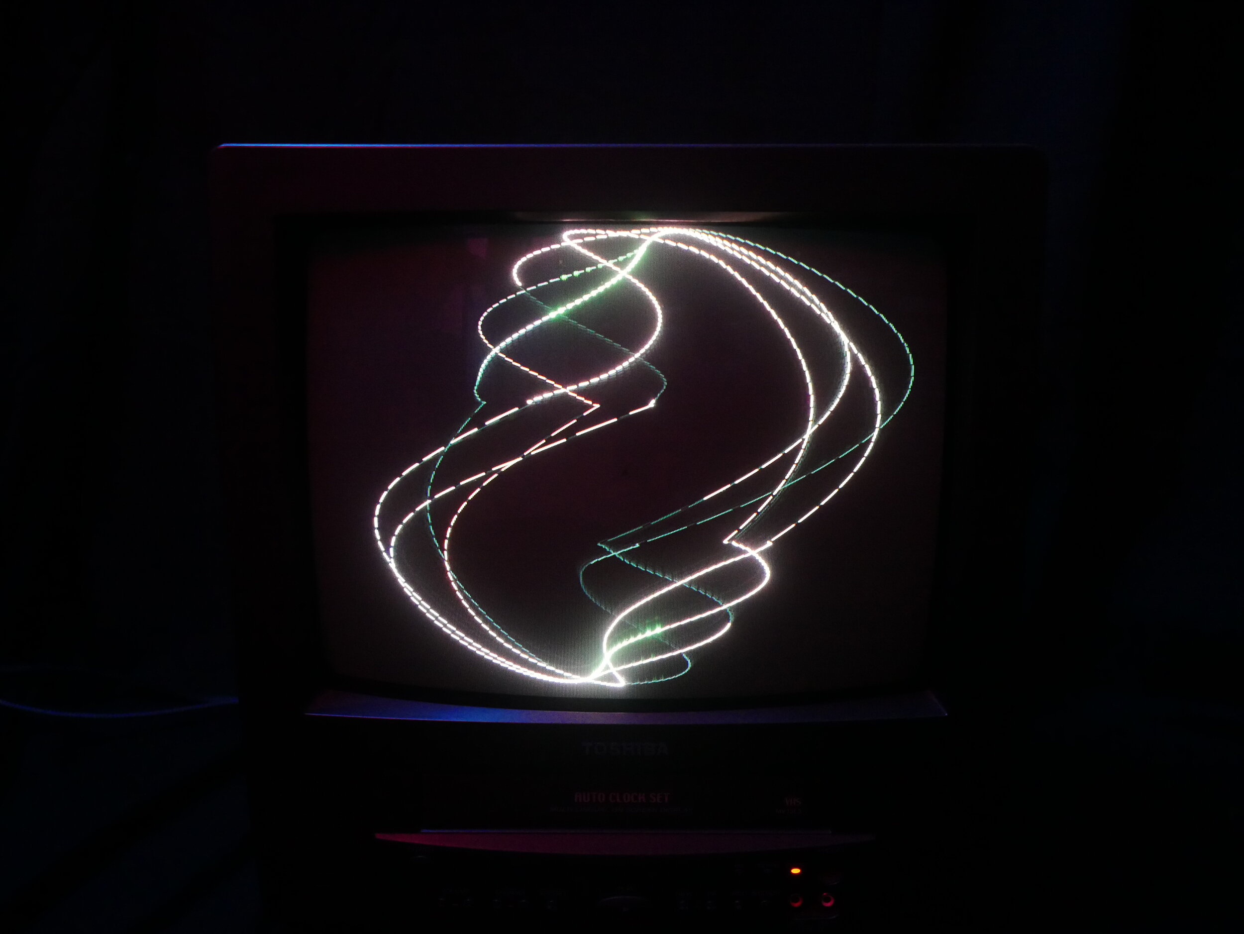
This is a variation on a fairly common build where audio is piped directly into the horizontal and vertical portions of the deflection yoke inside of a CRT Television. The additional features this one has are two internal audio amplifiers (very basic LM386 circuits), the ability to run audio to the TVs internal speaker with adjustable volume (lazily, only grabs the L channel). Because the stock composite video input is still in tact, this has the ability to receive color video signals and “color” the waveform which I go over in the video here on this page.
This build can be replicated fairly easily (even more easily without the internal amplification circuit if you want to amplify the audio externally), and also made to run in different ‘modes’ for a more standard horizontal or vertical wave display by leaving either of the yoke connections in tact. Plenty of information on that can be found online with a quick web/youtube search, but I’ve included the schematics for this particular build below.
If you do plan on recreating something like this for yourself BE CAREFUL. There are elements inside of CRT Televisions that hold enough charge to KILL YOU. Do not attempt if you are unfamiliar with electronics, and do your research beforehand on how to properly discharge the device and standard safety protocols for dealing with this sort of device.
November, 2020.
Basic schematic & some operating info
April 18, 2022 Note: The below schematic was for my first version with an integrated audio amplifier using two LM386s. While this does work, I’d highly recommend looking into other options as the LM386 has very noticeable distortion when used in this application, leading to a dirtier waveform display even at medium gain. More recently I’ve been using the TDA2822 which handles 2x audio signals on its own and powers the deflection nicely at a wide voltage range. A web search for this chip will turn up simple pre-fab PCBs with a dual taper 50k pot and everything else needed for easy integration into the circuit. One thing to note about the TDA2822 is that there are a few clones, and the most common one I seem to see on pre-fab boards is labelled with ‘WX’. Do not run these at 12v. the TDA2822 claims to have an operating range up to 12v (15v for some variations), but I’ve had multiple chips burn out running at 12v. Depending on your CRT you can get decent deflection even at 5v, but so far running TDA2822’s up to 9v has served me just fine. Powering this chip with something like a voltage regulator, or a pre-fab buck converter, is highly encouraged as voltage spikes seem likely to damage to TDA2822. I would also highly encourage socketing this IC for easy replacement; might save you some headaches. Also, be sure that you’re only plugging/unplugging an audio feed when the amplifier and CRT are powered off; accidental shorts to ground could cause problems or dead ICs if things are powered on.
