
DIY Modular Video Synthesizer
The Gleix Video Modular is a collection of DIY Eurorack format modules designed for analog video synthesis, VJing & live visuals, glitchy FX processing, and general audio-visual experimentation.
After building my first few proper commissioned visual devices like the 100PFB & The I.F.D., I realized that I wanted to do a more fully formed video-centric build for myself. I went back and forth on layout designs, enclosures, what to include, how to include it, and ultimately realized that the project was continuously expanding in scope as I learned more and more. I was removing features based on the enclosures and struggling with design, and I was also limiting the functionality as a result.
After realizing that I don’t want to limit myself, and I wanted to be able to expand my build as I learned new things, I decided to go the modular route. I put together a basic plan in between August and September of 2020 and finished the first twelve modules, GVM001 through GVM012, between then and December of 2020 amidst other projects.
As of now there is still 30hp of space left - I have a few ideas but haven't been able to decide on how to fill that space.
For now this is my playground for video synthesis and glitchy FX, a tool for learning about the interaction of different signals, and a way to easily prototype new machines.
9/23/2021: Check out this recent performance that heavily utilizes this build! [Link]
Current Modules
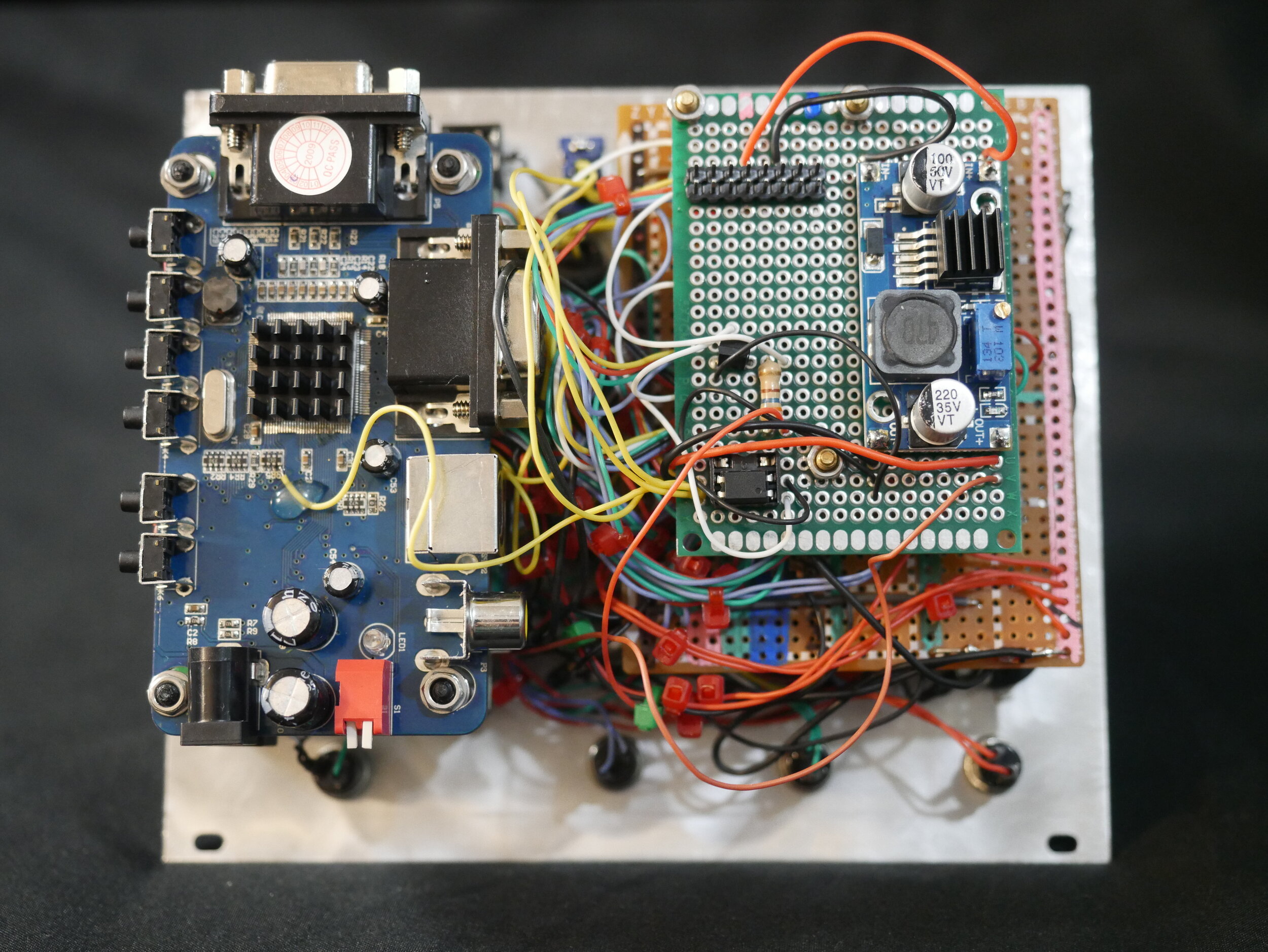
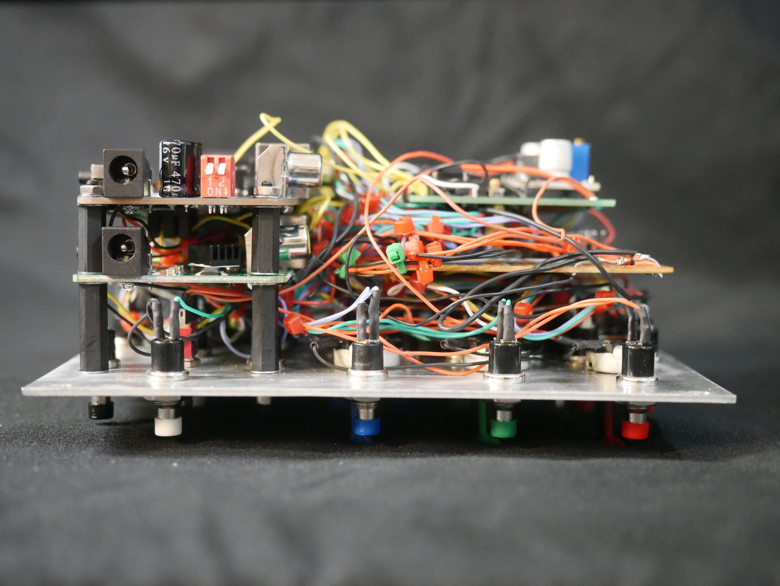
GVM001 // FB-CV
30hp // Feedback generator, i/o color signal hub
Also GVS004 due to the standalone functionality of the module. This is a primary module in the set up designed to create video feedback using a basic set up between two analog video signal converters. It functions similarly to standalone video devices of this style that I've done but with a greater focus on the CV & IO features. These make it a great place to build both feedback & more complex shapes and patterns with signals from the other modules. Check out Lofi Future for some info on the basic setup - the feedback loop itself can be DIY’d pretty cheap & easily.
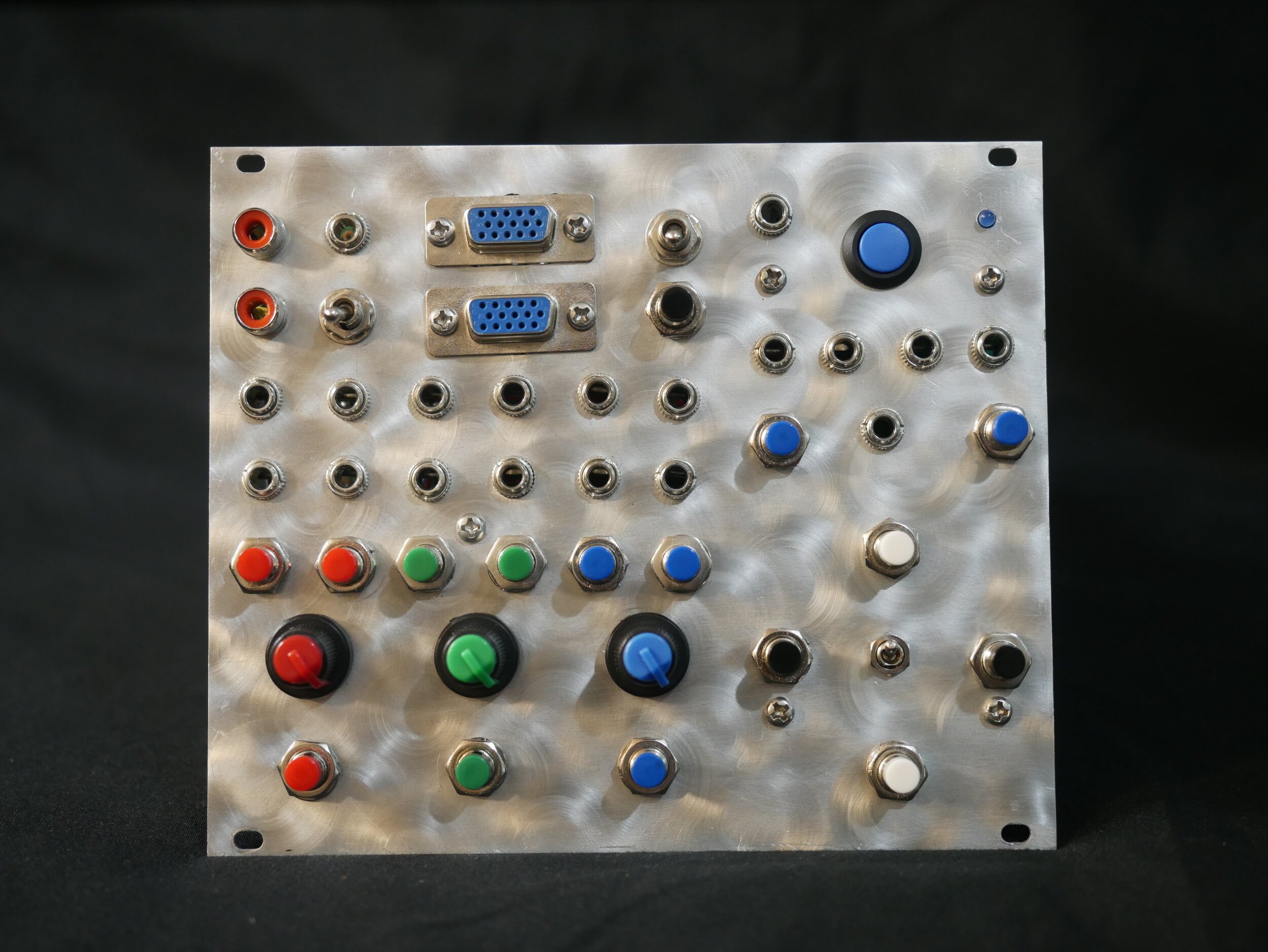
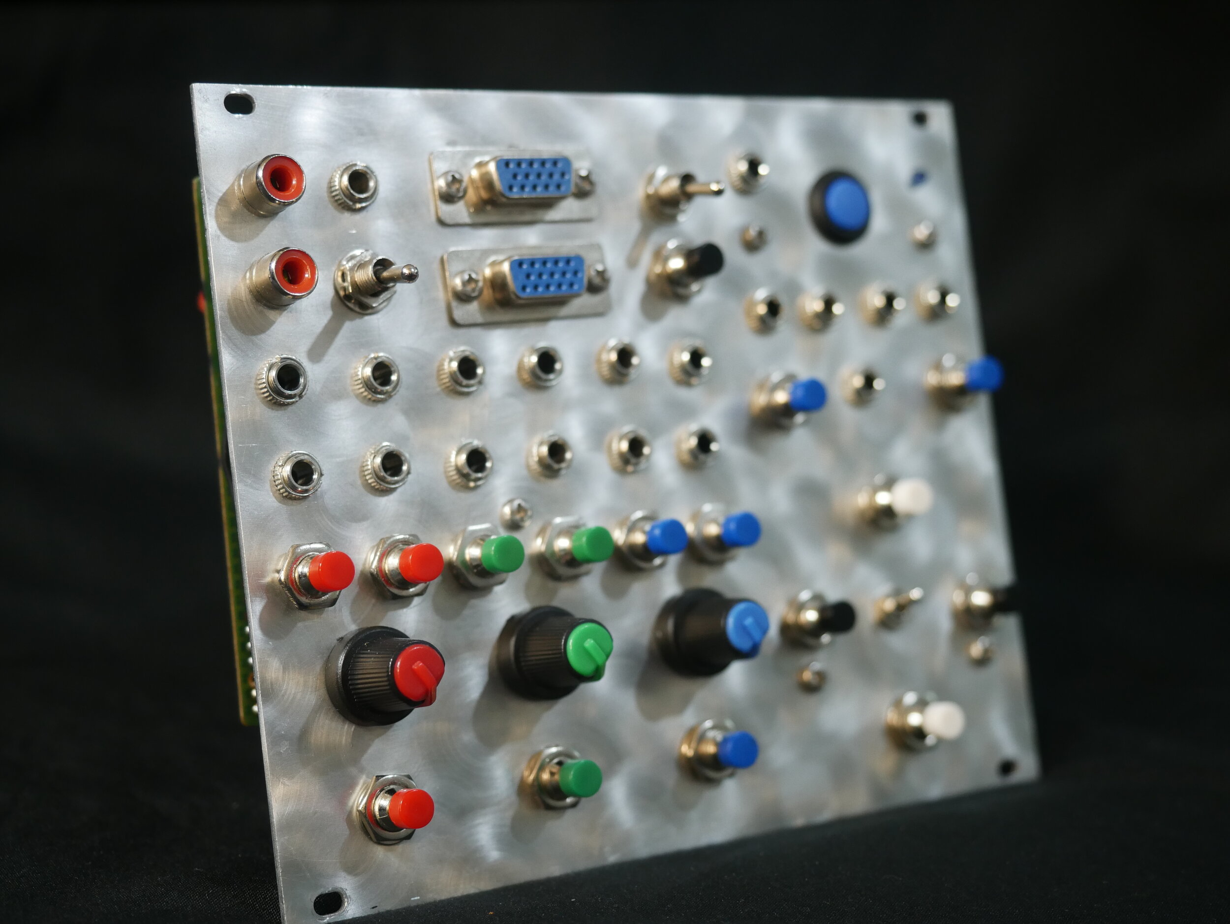
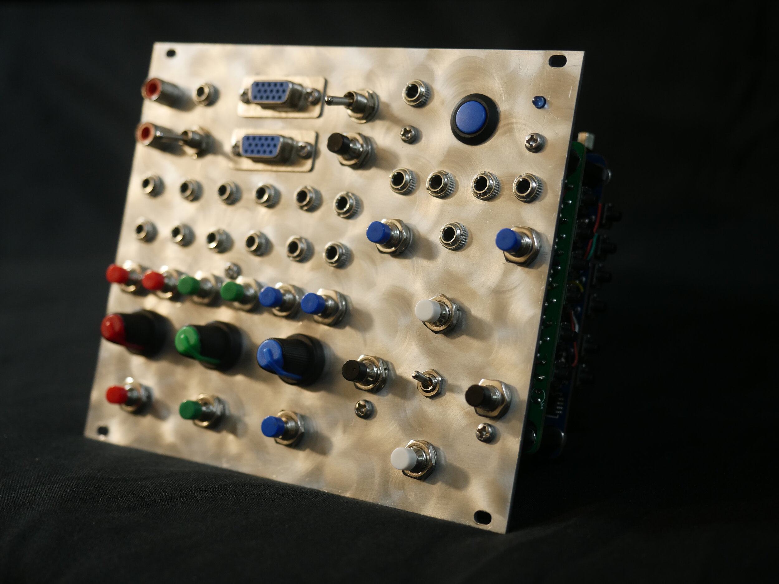
Physical controls
1x Power button
3x Mix controls for RGB
3x Pulse buttons for RGB
4x Image shift buttons (up, down, left, right)
1x Image size adjust button
1x "grounding" switch (Allows mix knobs to connect to ground, alters behavior)
2x Image freeze controls (1x momentary button, 1x switch). Also doubles as a mode select if feature is on while turning on the module (standard vs pixelated/blocky image).
6x Additional menu controls for saved color settings, resolution, etc...
CV/Gate
6x Mix control CV input jacks (2x per color)
4x Image Shift CV/gate inputs
1x Image size CV/gate input (with on/off)
1x Image freeze CV input
I/O
6x color input jacks (2x per color, correspond to either end of the mix). These double as audio output jacks for correlating color.
3x Composite output (2x RCA, 1x TS)
1x VGA Output
1x VGA Input
GVM002 // Glitch Matrix, "Buffer Fish"
24hp // VGA glitch signal processor, color mixer
Also GVS005 due to the standalone functionality of the module. This module is similar to my first video-centric build, the VGS-35, and is based off of the same modified VGA to Composite converter design. It exposes a number of interesting points on a 74HC125 quad buffer and a W9816G6XH-6 SDRAM chip, as well points for RGB, Hsync & Vsync on the VGA connection, and a few other useful points for either patching with itself or injecting external signals for unique visual glitches.
Physical controls
1x Power switch
3x Mix controls for RGB
4x Image shift buttons (up, down, left, right)
1x Image size adjust button
2x Image freeze controls (1x momentary button, 1x switch). Also doubles as a mode select if feature is on while turning on the module (standard vs pixelated/blocky image). Great for creating a mosaic-effect on the incoming image.
CV/Gate
3x Mix control CV input jacks
1x Image freeze CV input (Acts as a slitscan with high speed signals)
I/O
24x patch points associated with video RAM, video buffer, H-sync, V-sync.
6x color input jacks (2x per color, correspond to either end of the mix). These double as audio output jacks for correlating color.
2x Composite output (1x RCA, 1x TS)
1x VGA Output
1x VGA Input
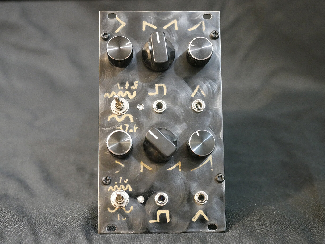
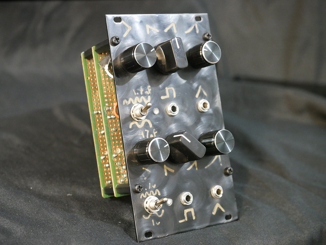
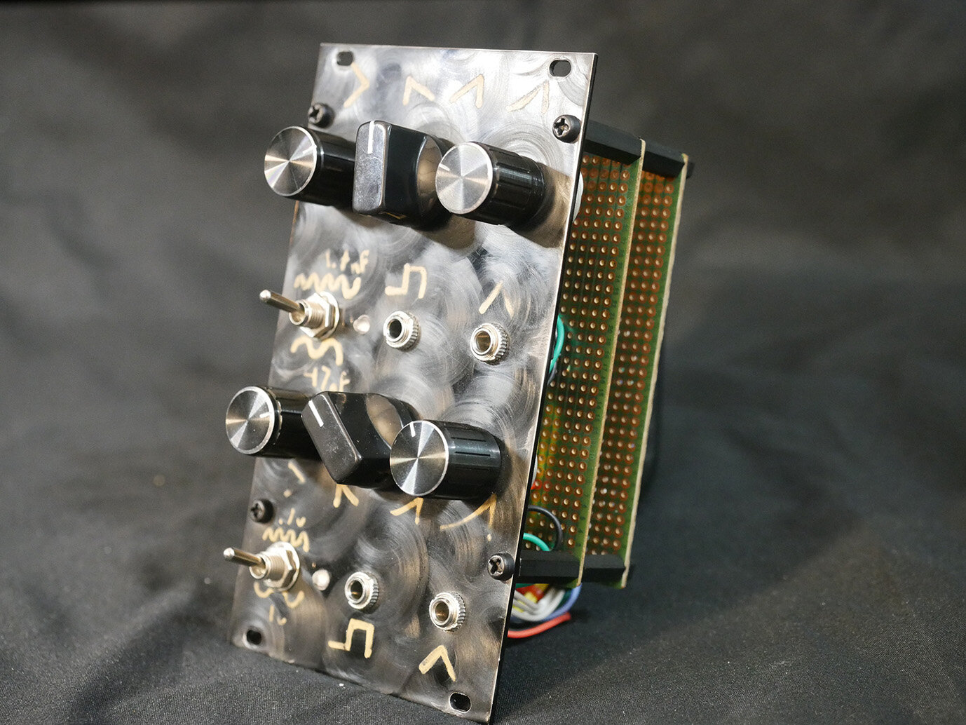
GVM003 // Dual LFO
14hp // 2x simple LFOs
Gotta have 'em. This one is based off of Niklas Ronnberg's fantastic design. The only real changes in mine are the capacitor value selections for setting different speed-ranges, and that I exposed depth as a knob rather than setting it with an internal trim pot. The shape knob allows for full pulse-width adjustment of the squarewave output, as well as transforming the triangle into a sawtooth or inverse sawtooth, though both the shape & depth knobs will cause changes in the frequency. This design - due to the large range of shape and frequencies - make it ideal for creating a full range of scanlines and basic color channel pulsing.
2x LFOs each with:
1x Frequency Knob
1x Frequency LED
1x Shape adjustment knob
1x Depth knob
1x Squarewave output
1x Triangle output
1x Frequency range select (low/high). LFO 1 uses 4.7nf and 47nf (higher speeds), and LFO 2 uses .1uf and 1uf (lower speeds). Both of these can reach scanline rates depending on the depth. At higher depths LFO 1 is preferred for scanlines.
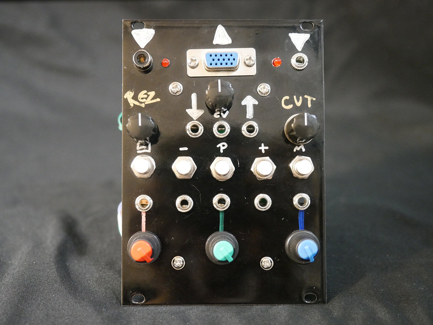
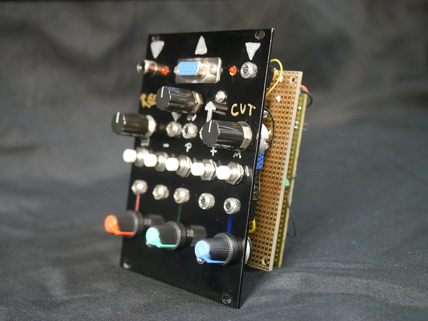
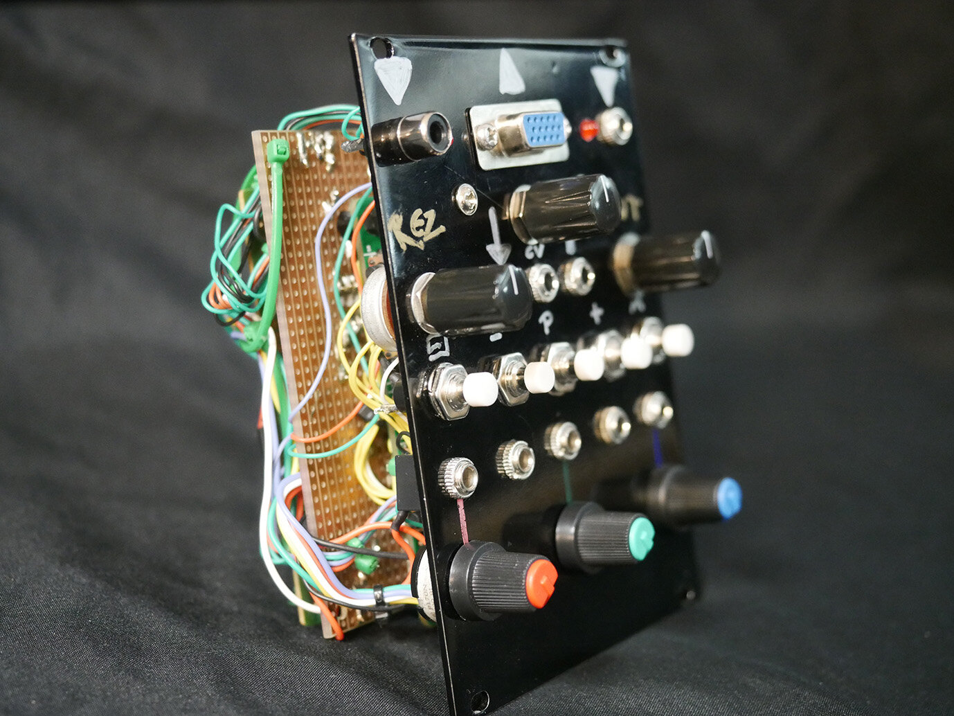
GVM004 // Bizzaro combo module
18hp // Composite to VGA converter & color mixer, Korg MS-20 filter clone
I wanted a composite to VGA standalone module for ease of creating a feedback loop with GVM002, and I also had a filter I made a couple years ago but never used and just sort of... added that to the module since there was space. Nice for building irregular scanlines at high resonance, filtering audio from GVM001, and basic composite > vga functions. The filter is based off of LMNC's design - sounds & functions great!
Composite to VGA
3x Mix knobs for RGB
3x CV inputs for RGB
5x Menu buttons for saved color settings, resolution, etc...
2x Composite input (1x RCA, 1x TS)
1x VGA output
Filter
1x Resonance knob
1x Cutoff frequency knob
1x Cutoff frequency CV input
1x CV input attenuator knob
1x audio input
1x audio output
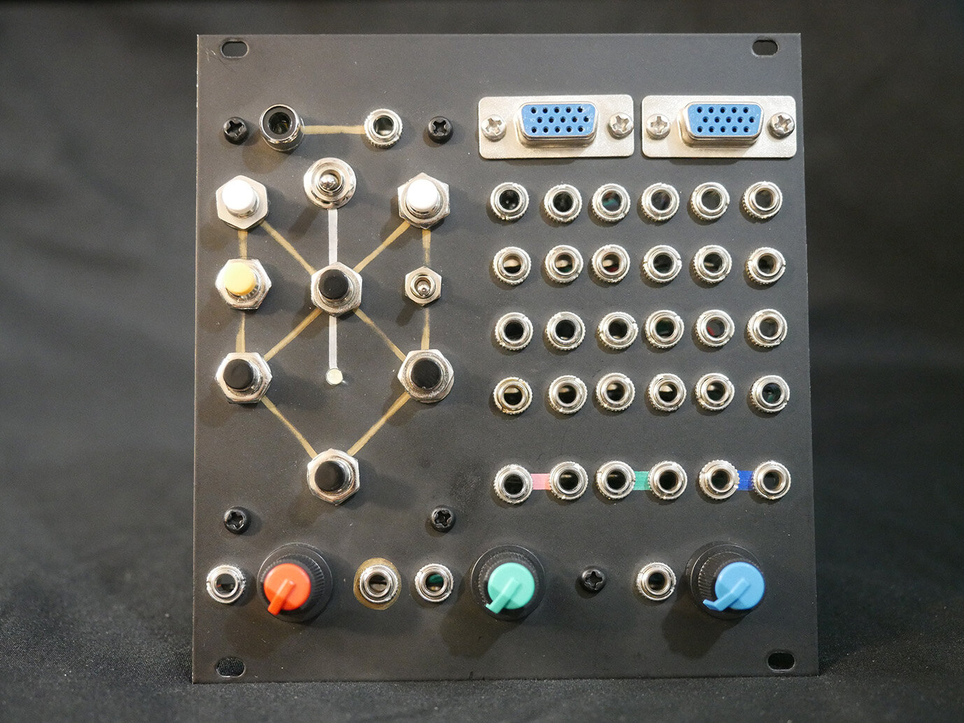
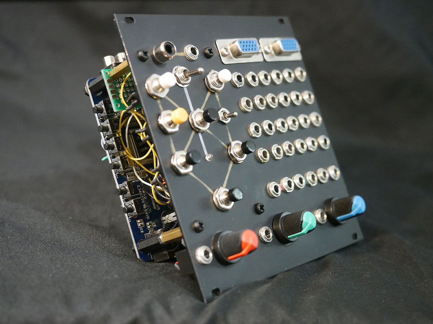
GVM005 // Patch saver, Composite<>TS
12hp // Mini control center
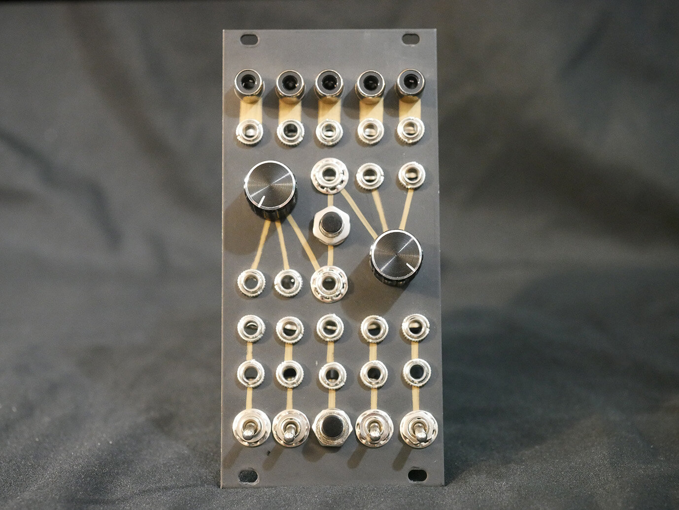
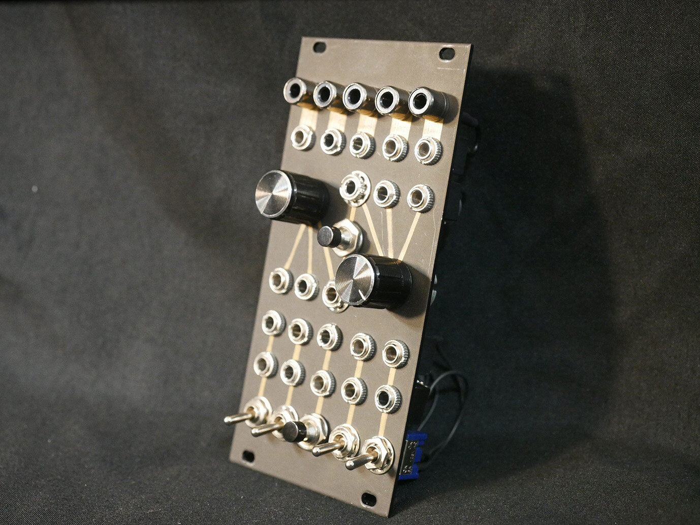
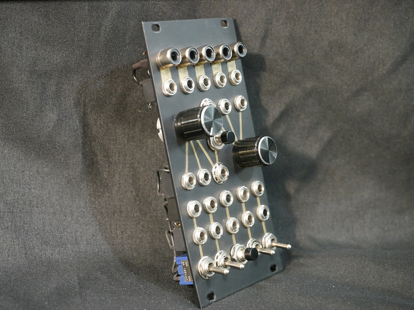
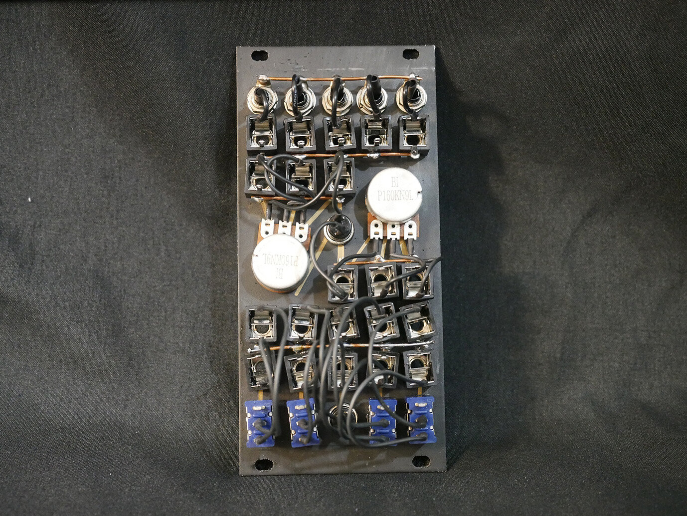
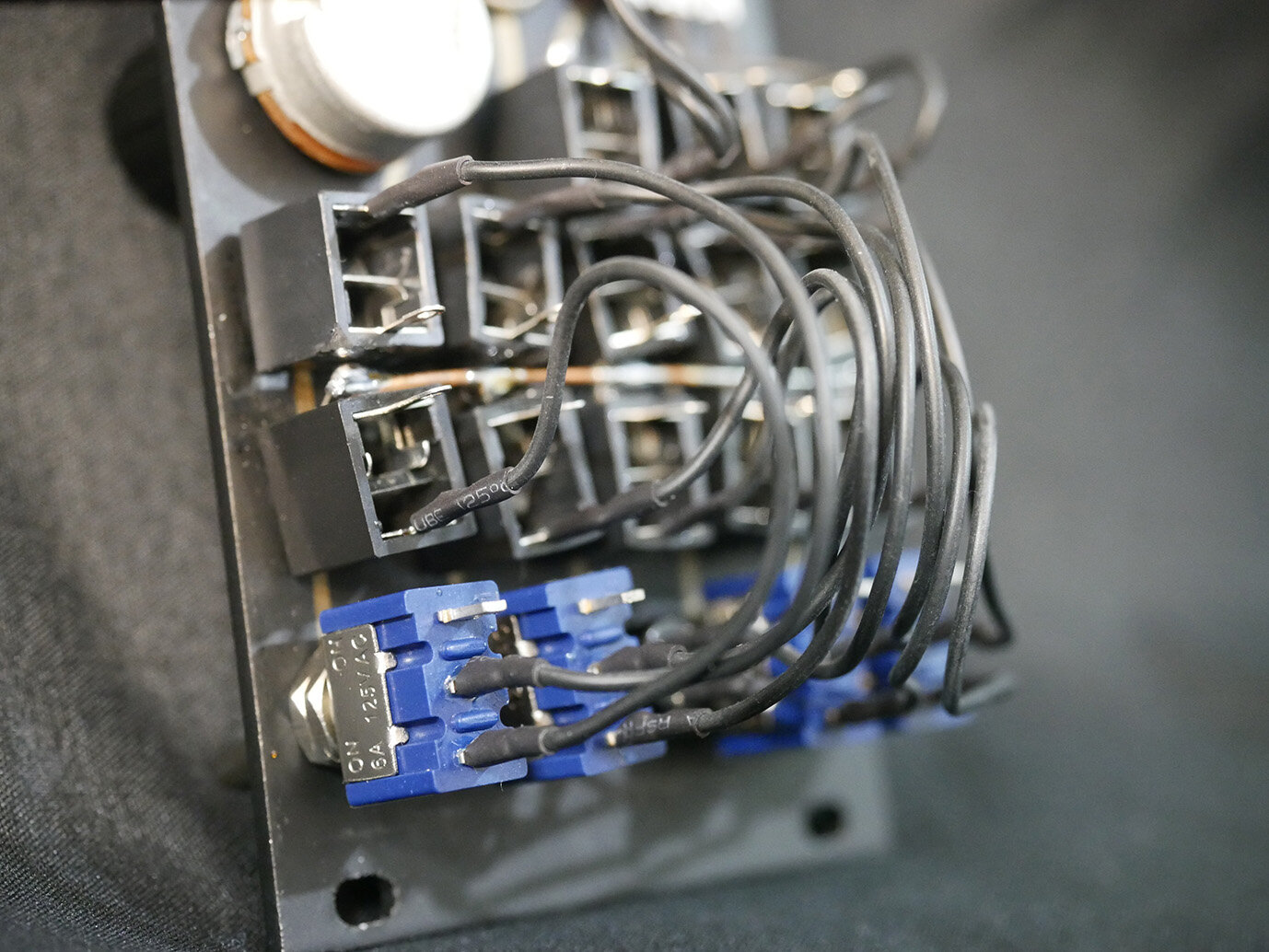
This is a sort of mini version of the control panel I made for the MB-37. It's a fairly simple passive module for routing patch points to switches, potentiometers, buttons, and converting between connection types.
4x Two patch points to a switch
2x Two patch points to a momentary button
2x Three patch points to a 10k potentiometer
5x 3.5mm TS jack <> RCA jack
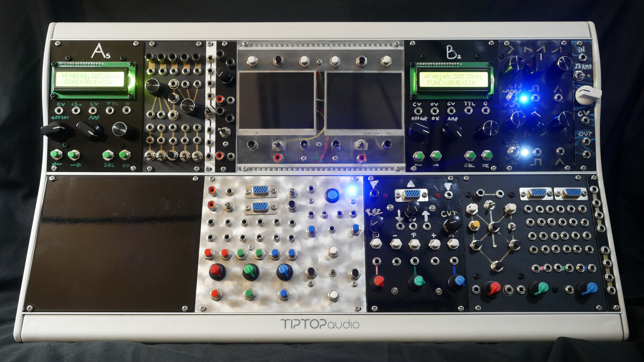
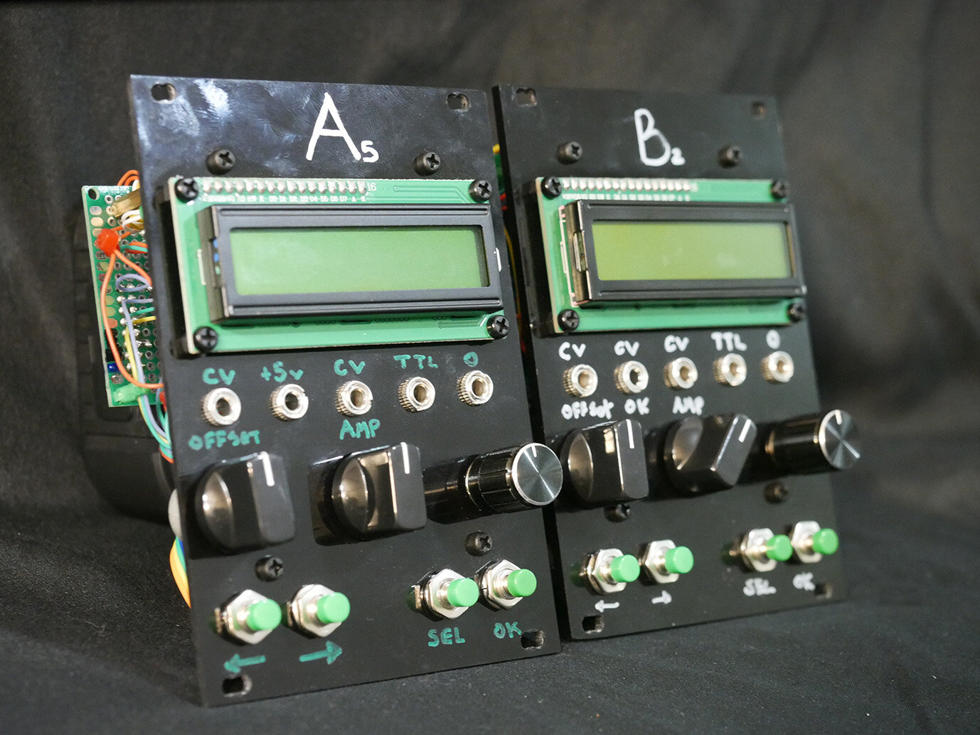
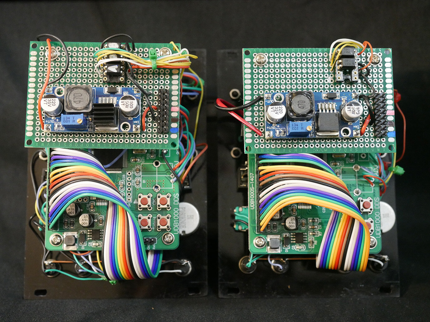
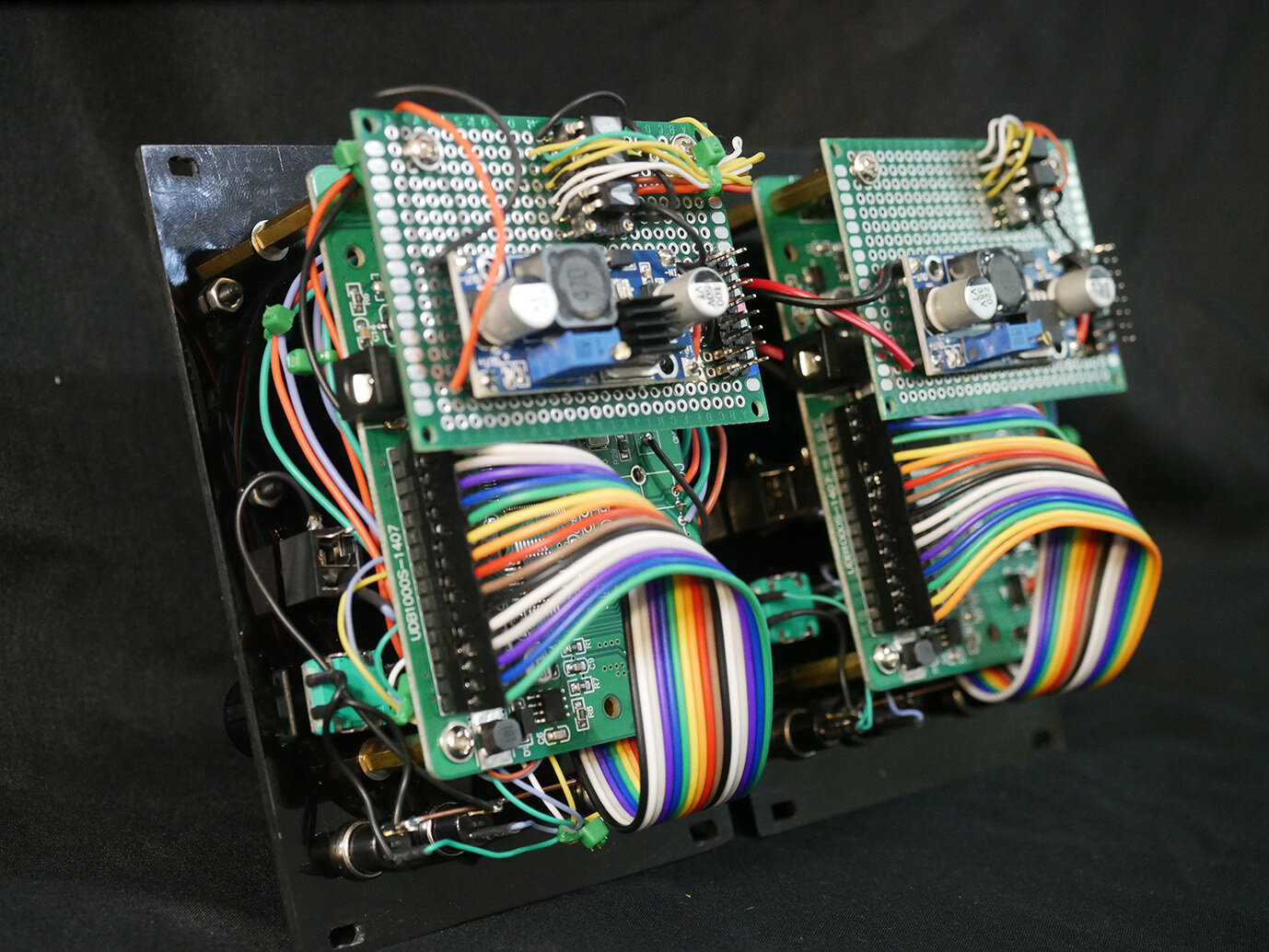
GVM006 & GVM007 // Signal Generator A and B
18hp x2
These things are part of what makes this thing tick and there's not a whole lot to them, really. These are fairly cheap signal generators that you can buy a bare bones device under a few different brands that max out between 2MHz and 8MHz depending on the model. I experimented with a few different signal generator circuits but ended up going with these. They're the most useful for this application and are fantastic for a few reasons - namely that you dial in exact frequencies, select from different waveforms, dial in duty cycles, offset, amplitude, save and recall exact frequencies, and a number of other things. One of these is model UDB1002S and one is UDB1005S (a quick web search ought to give you some stores if you’re trying to buy one) which max out as 2MHz and 5MHz respectively, though going above 200KHz doesn't yield anything too interesting. I've exposed the primary controls for the device as buttons, the signal output, TTL output, and added CV for the signal offset, amplitude, and the rotary encoders "OK" button which can be used to trigger changing different features such as the wave shape. If I could redo this I'd add triggers for a few other things, like trigger inputs for both rotary encoder movements. I may do that in the future if I get around to making a trigger sequencer.
These are one of the best ways to dial in either scanning or stable vertical, horizontal, and diagonal lines, and using both of them in tandem (or in conjunction with other signals ie. LFO) allows for building shapes where the two signals overlap.
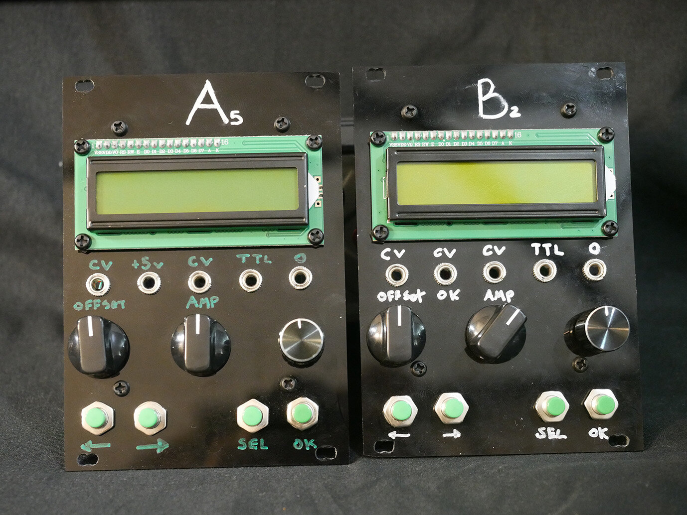
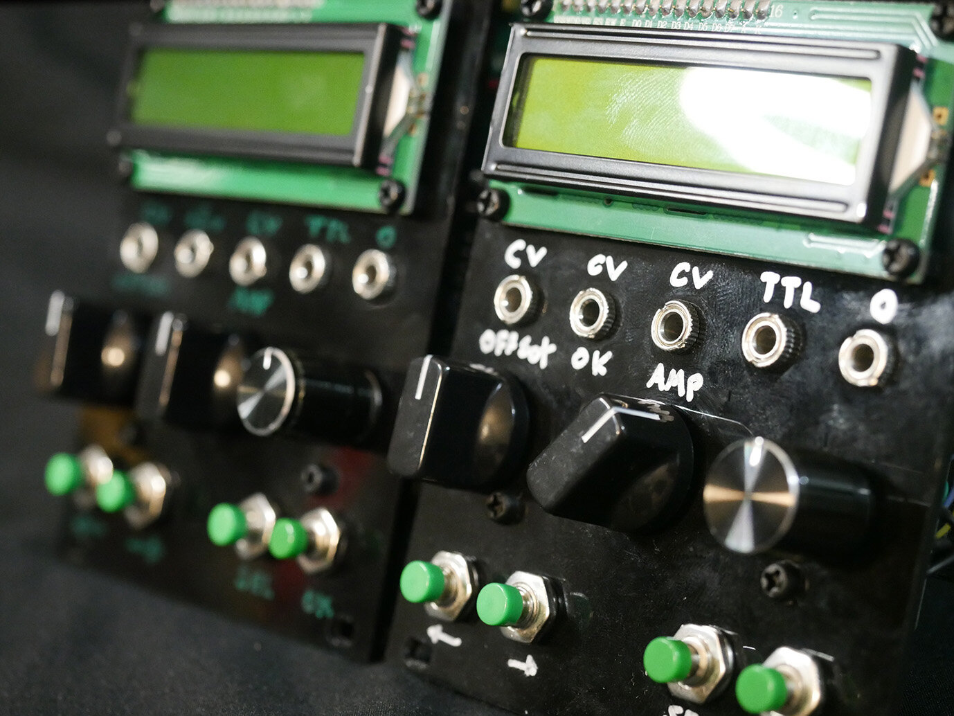
Physical controls
1x Rotary Encoder
1x Offset knob
1x Amplitude knob
4x Navigation buttons
CV/Gate
1x Amplitude
1x Offset
1x "OK" button (encoder)
I/O
1x TTL output
1x Primary signal output
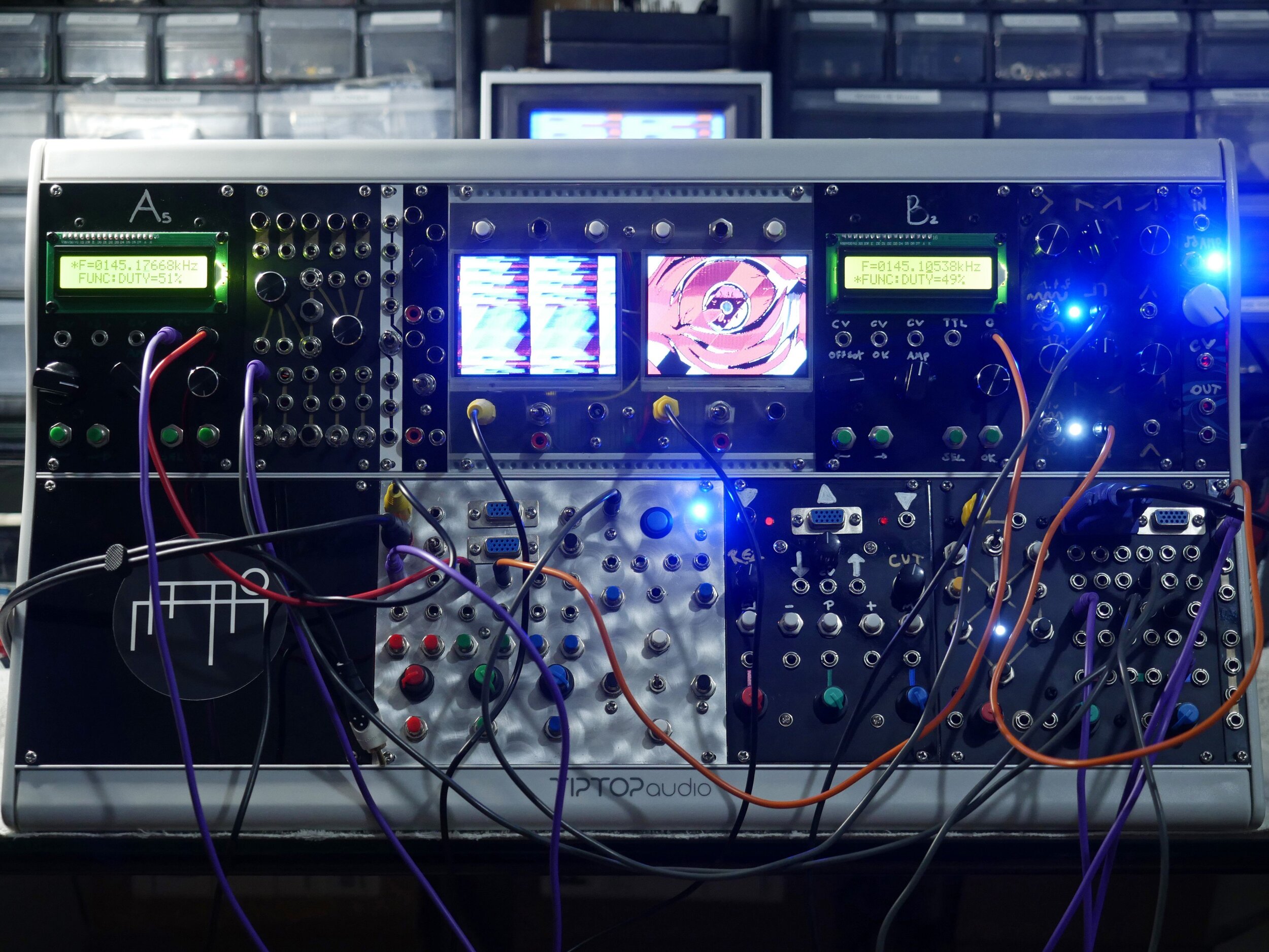
GVM008 // Dual composite monitors
32hp
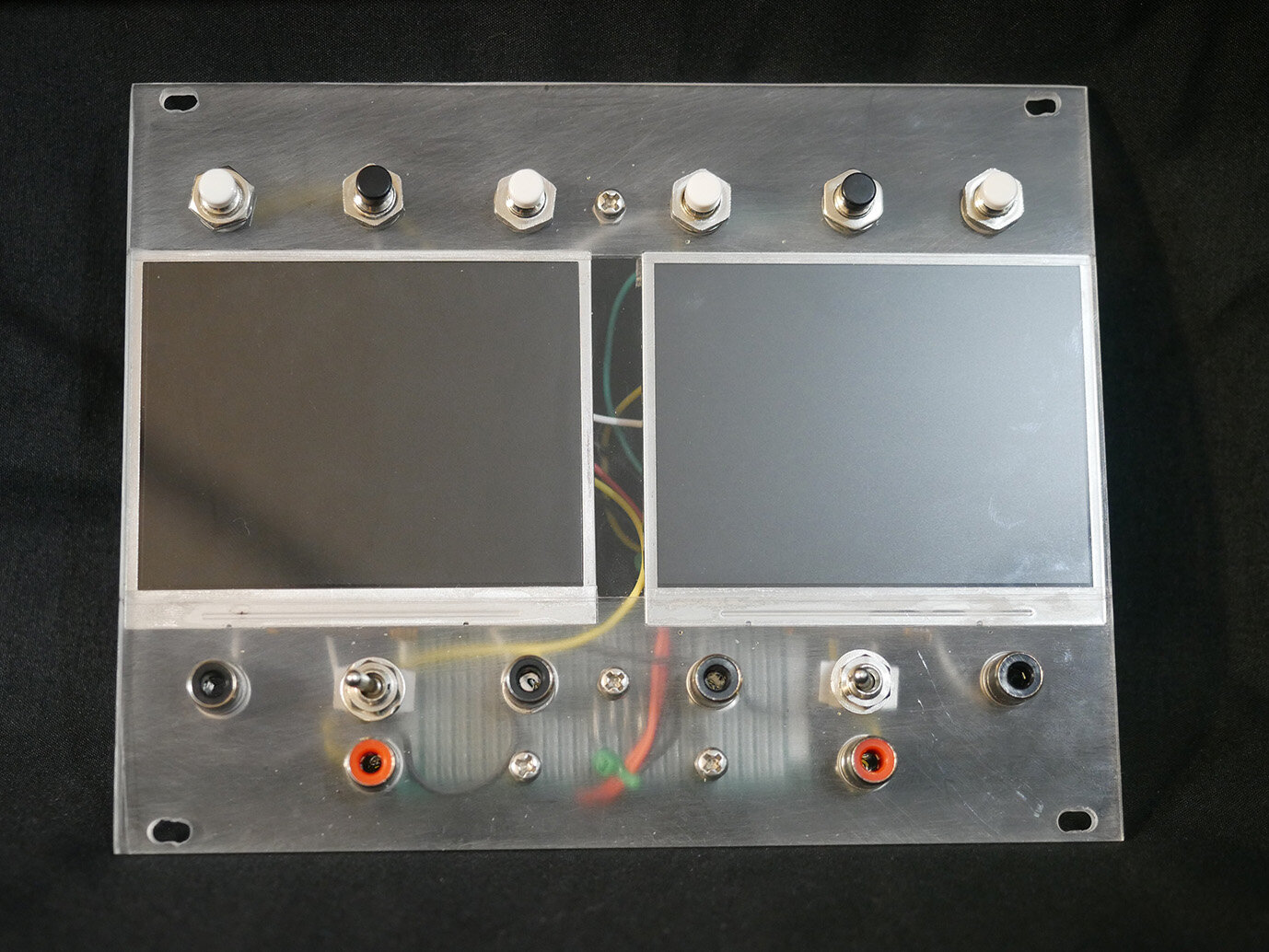
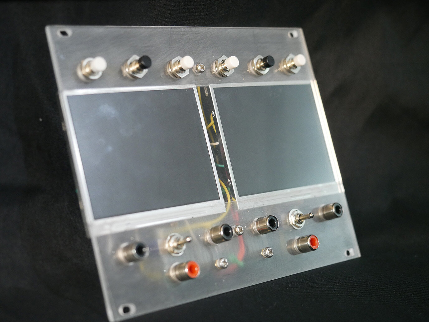
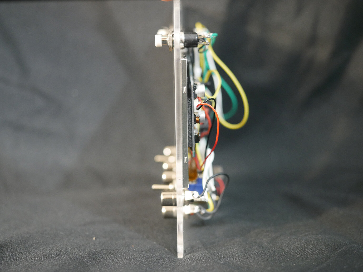
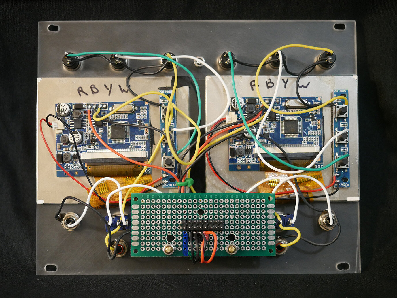
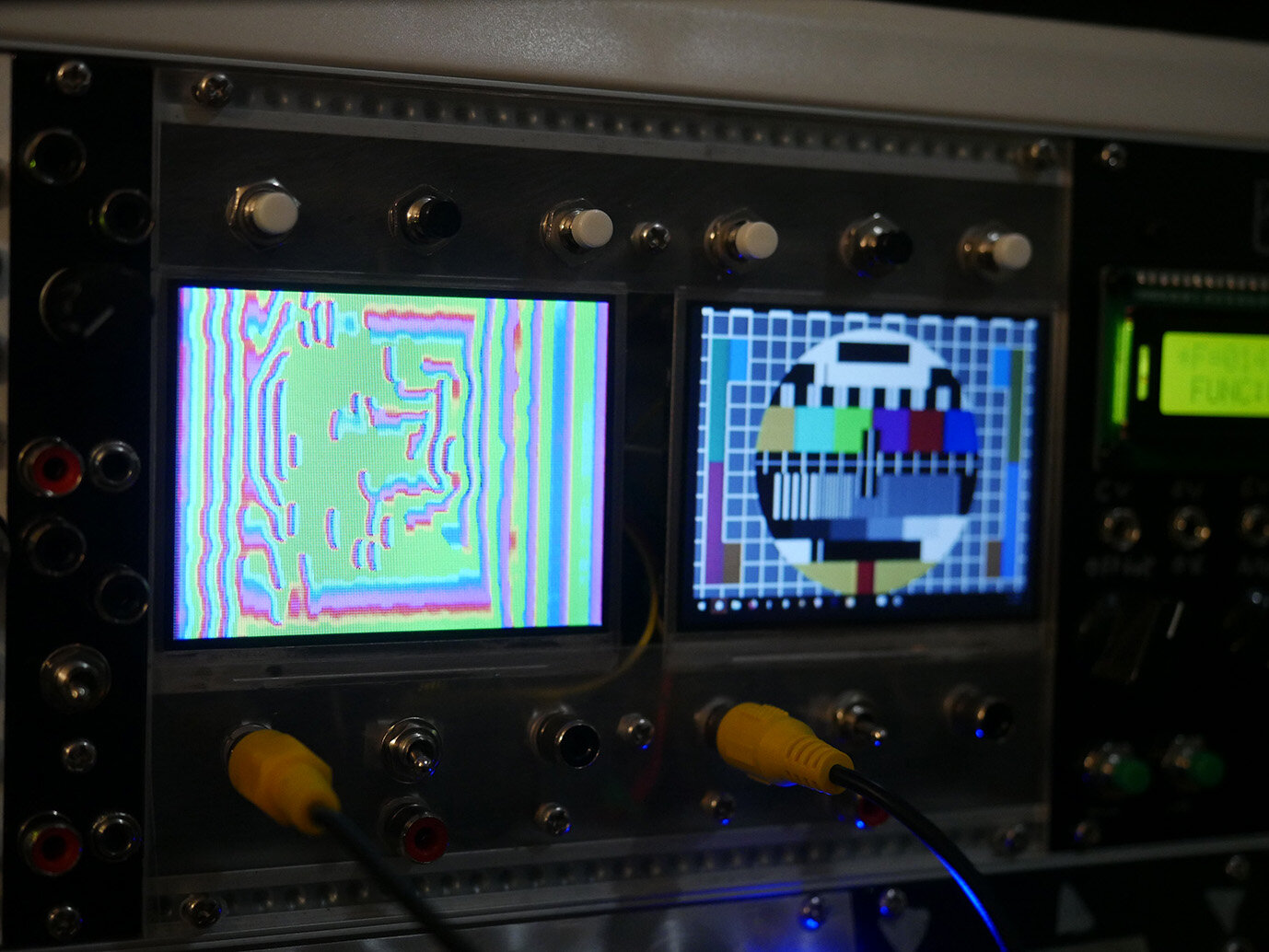
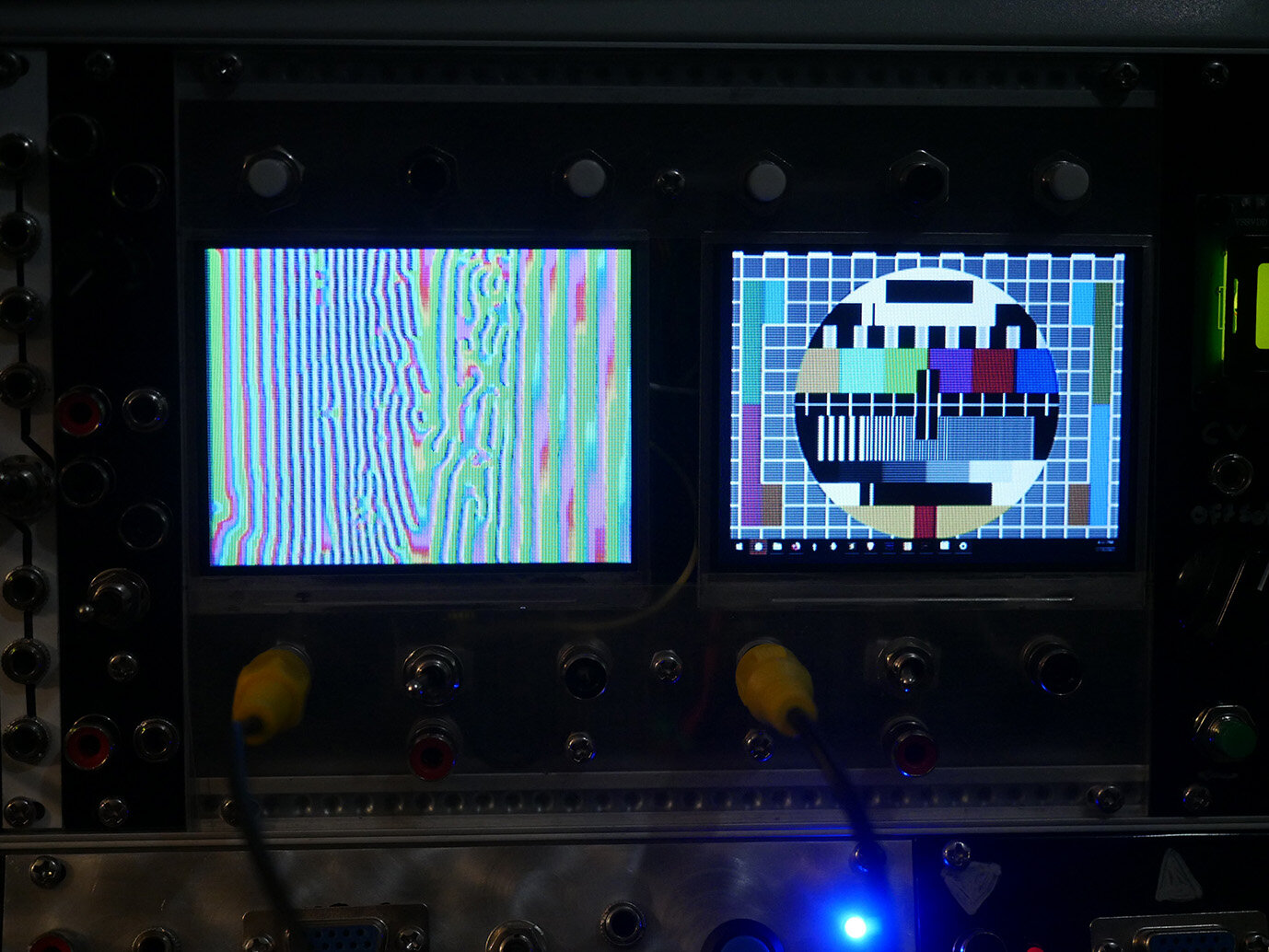
This module was made using two little 3.5" composite video monitors that are sold as backup-camera-screens to mount in your car. Super cheap and easy to find online from most big retailers, and they look decent! Added an A/B select for two inputs per screen and a passthrough for the selected source.
This module was made from clear acrylic with the top and bottom sanded a little bit, and the little screens were mounted with double-sided tape.
GVM009 // Audio Amplifier
4hp
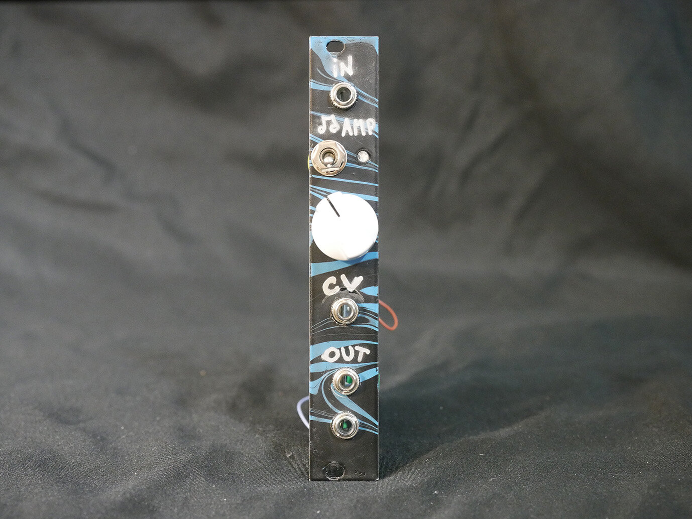
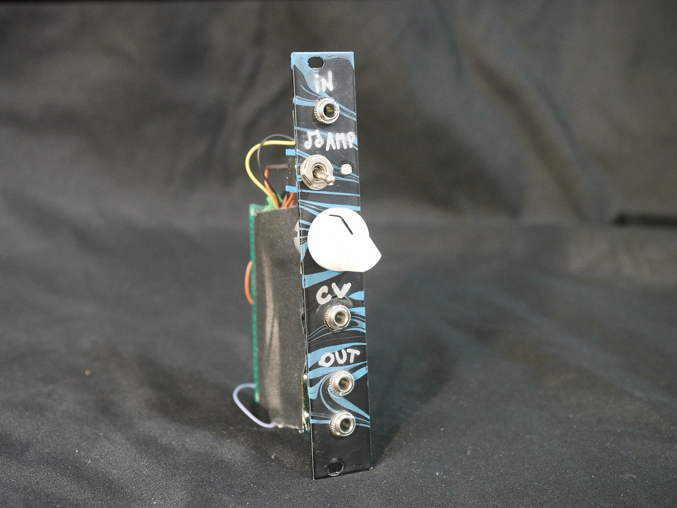
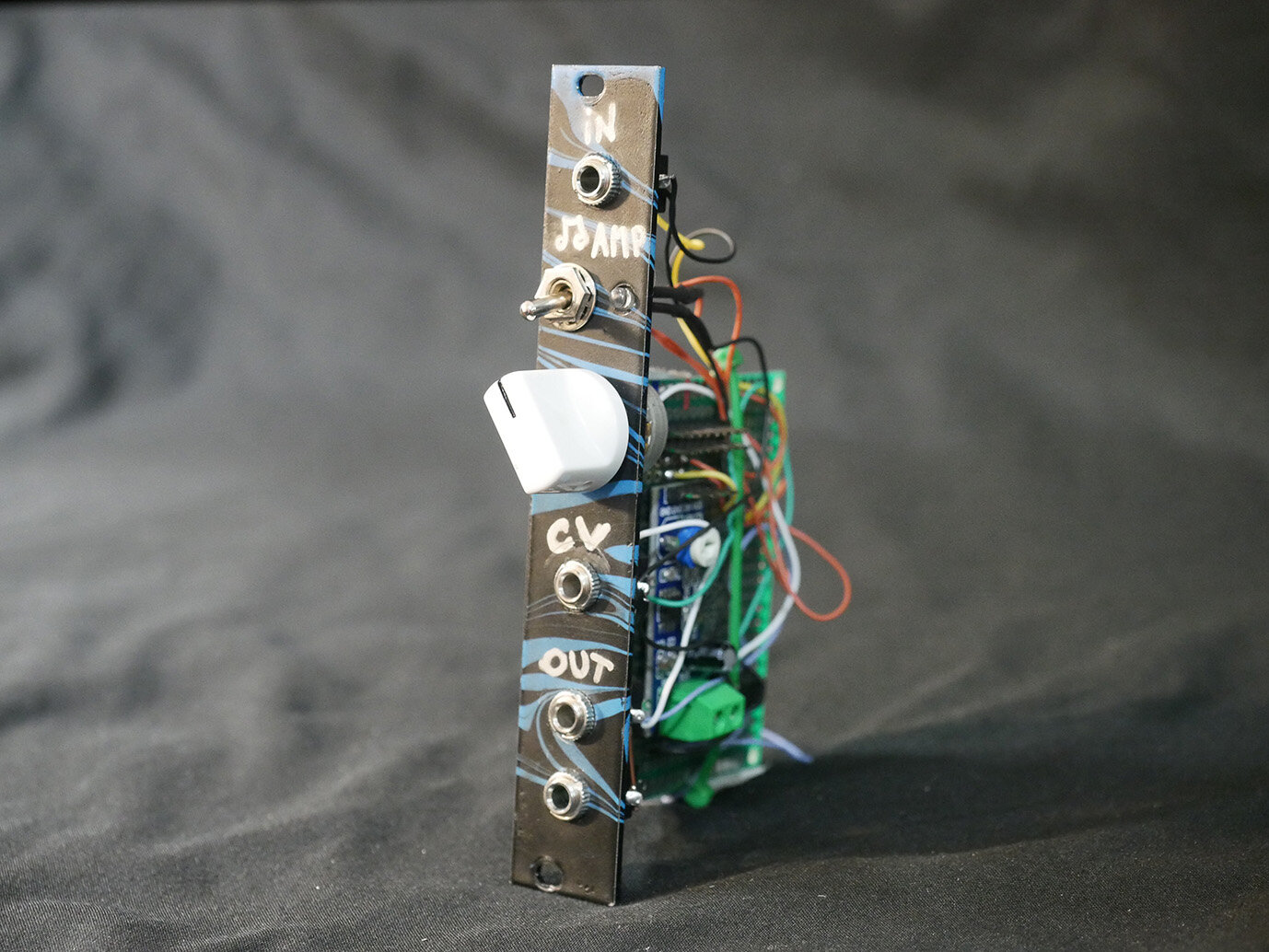
Very simple LM386 based audio amplifier for integrating external audio signals as video modulation sources. Initially had a diy circuit but ended up replacing it with a prebuilt one for stability and size. Gave this one a little marbling.
1x On/Off switch
1x Gain knob
1x CV in
2x Audio output
GVM010 // Source selector
4hp // 1x Dirty mixer, 1x A/B switch
Self explanatory. One dirty composite video signal mixer, and one A/B selector, both with CV which will turn the A/B switch into a pretty glitchy mess as well.
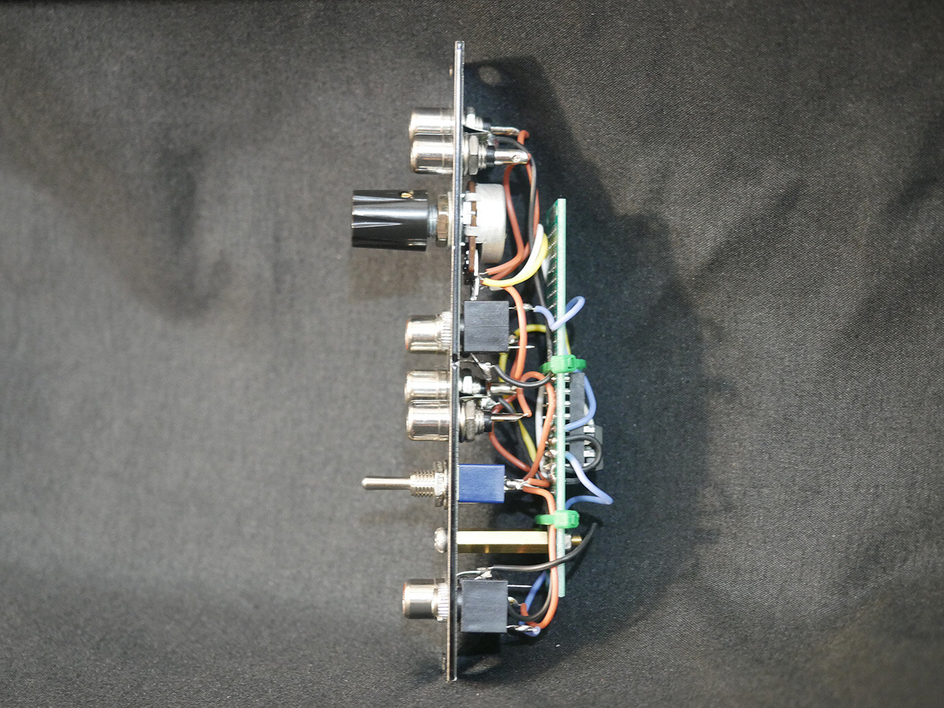
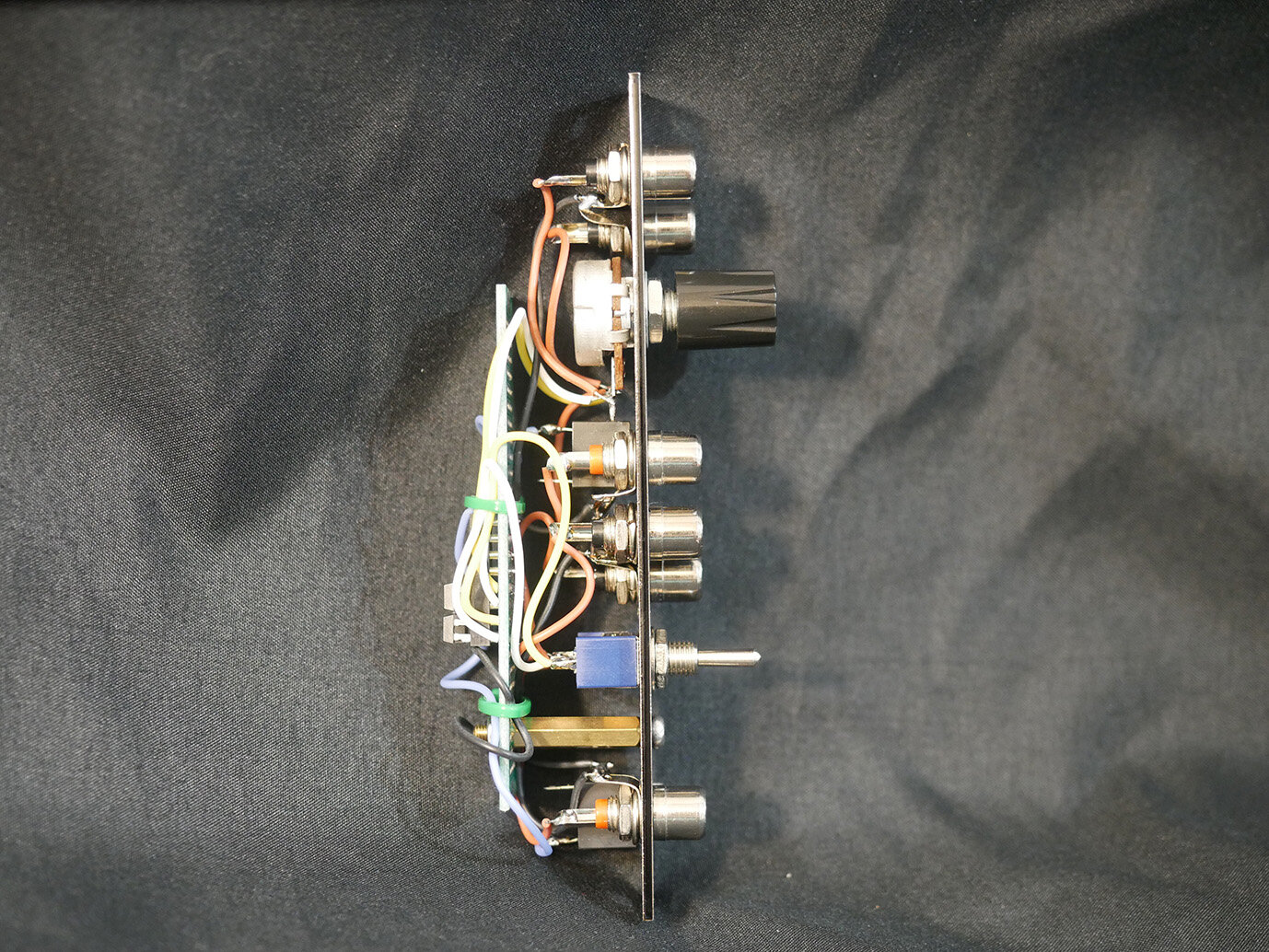
GVM011 & GVM012 // Passive multiples
2hp x2
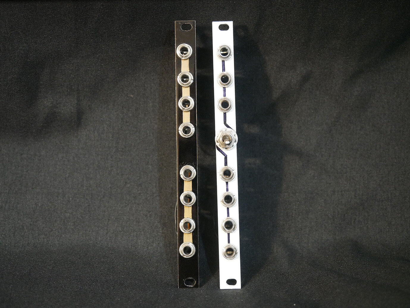
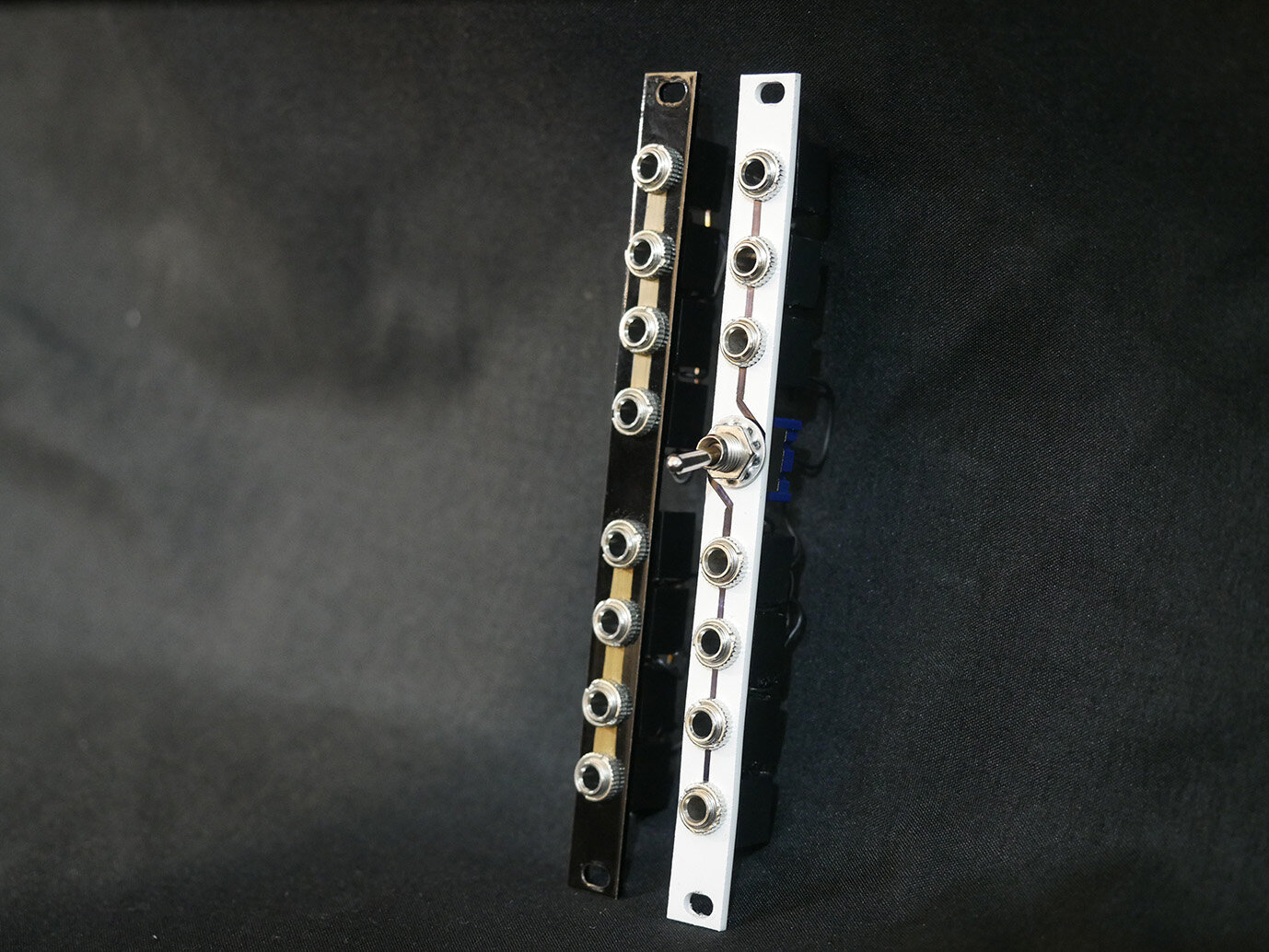
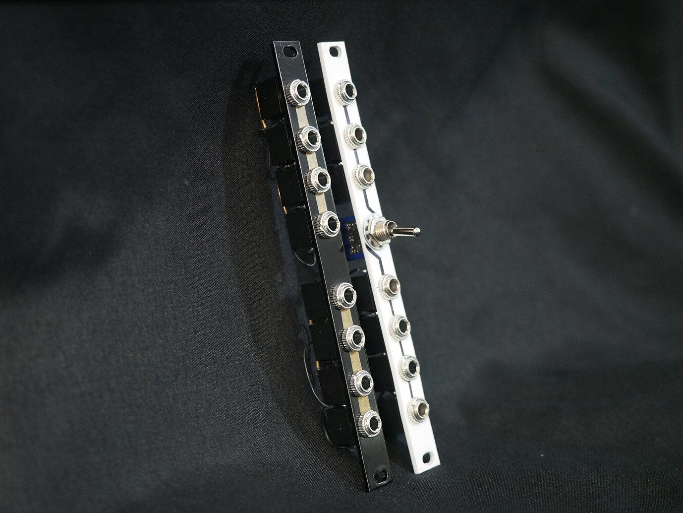
Super simple passive mults. The black one has 2x 4pt mults, and the white one has a 3pt and 4pt that can be combined with a switch for a 7pt mult.
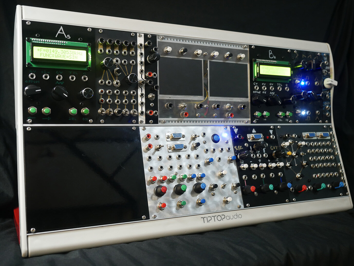
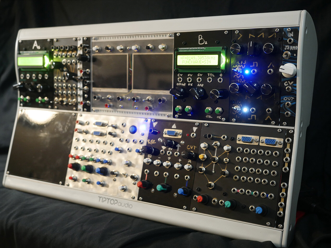
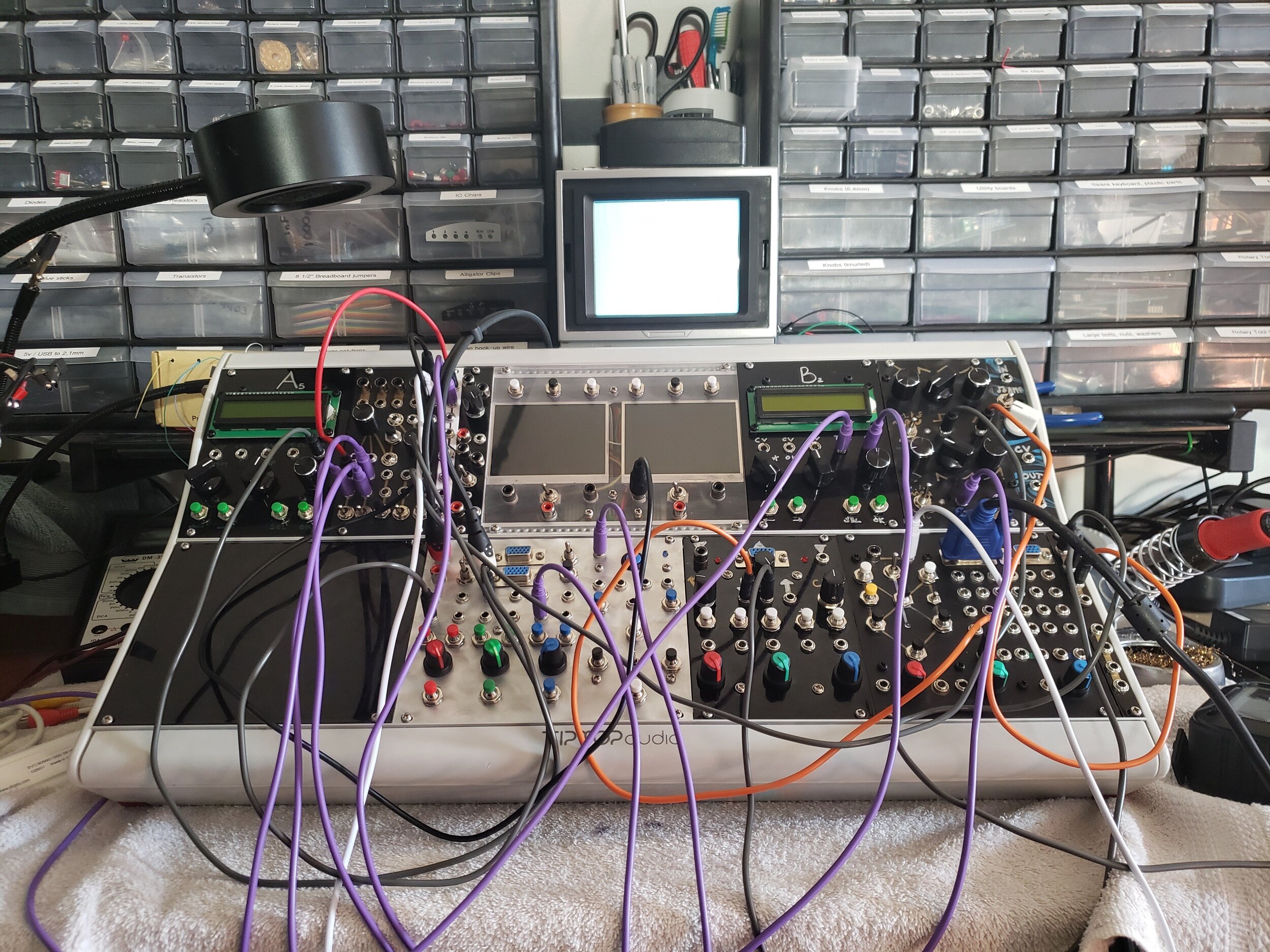
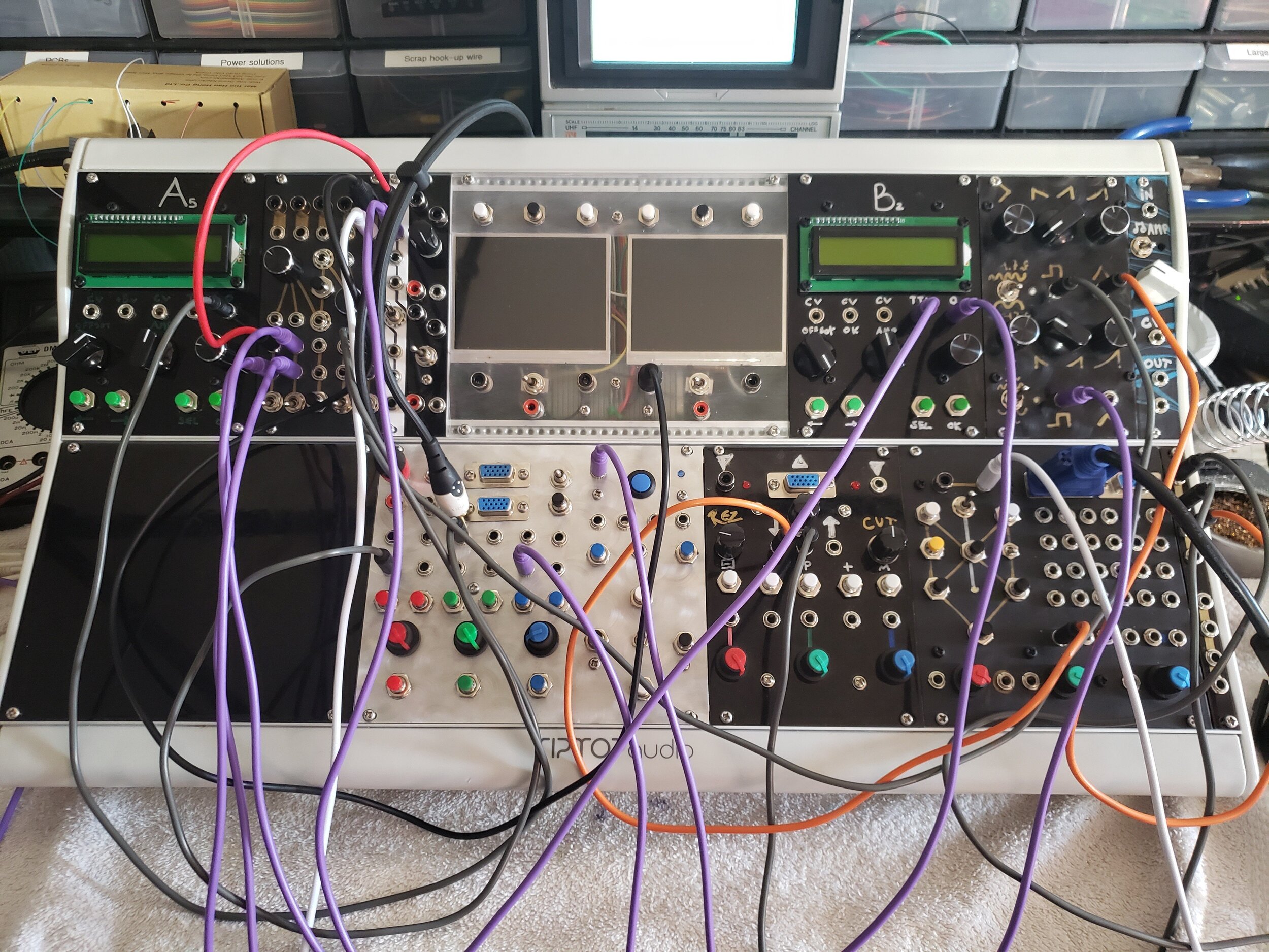
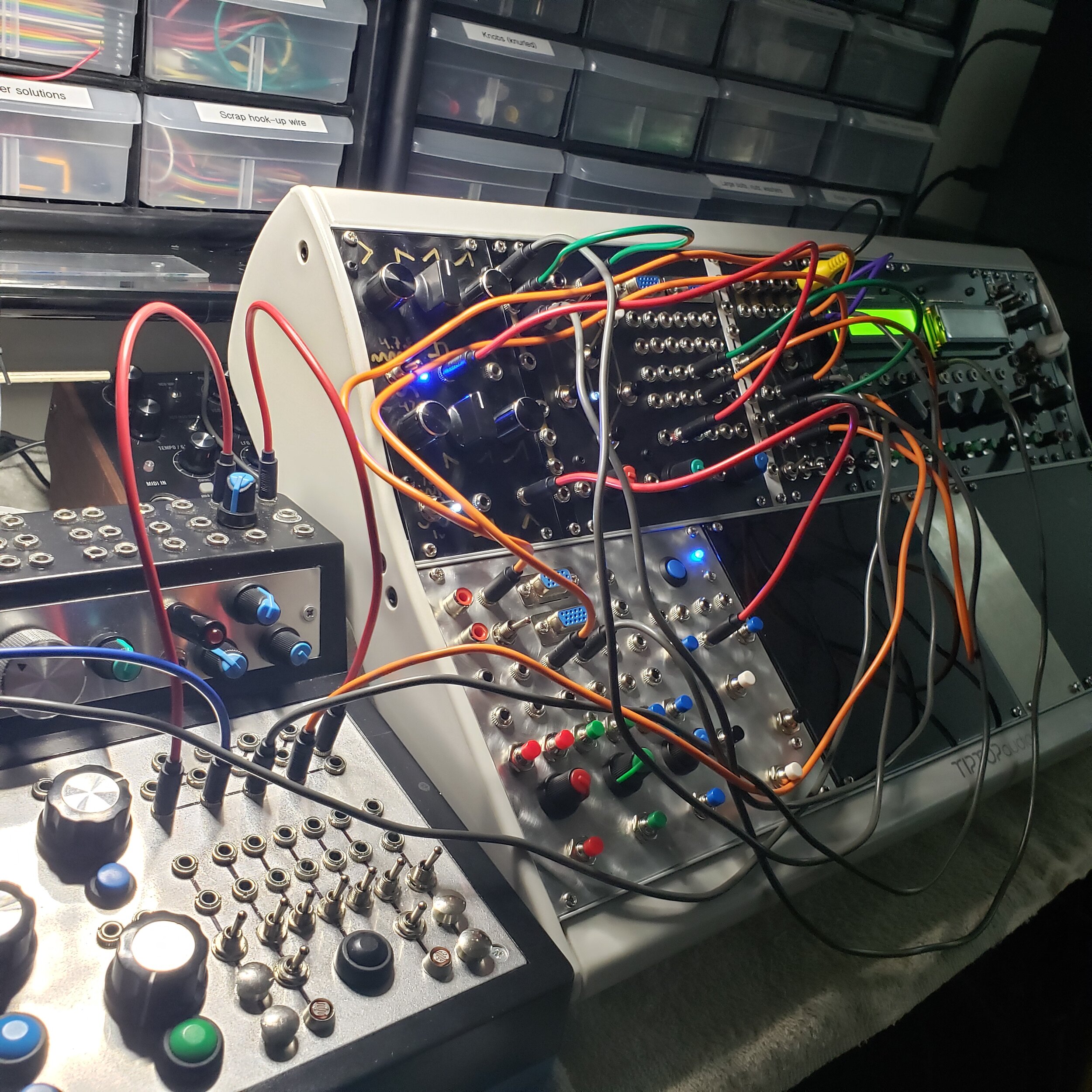
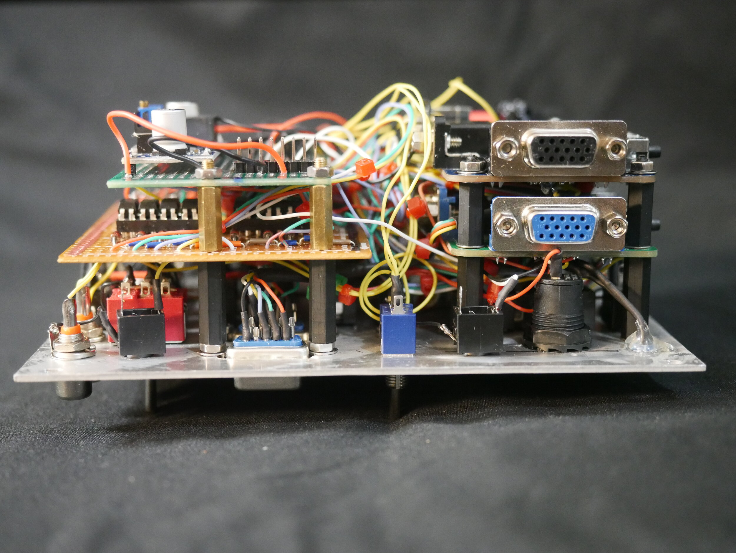
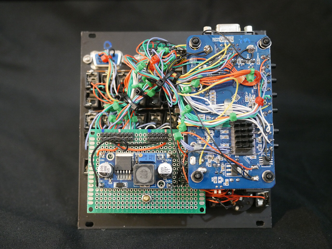
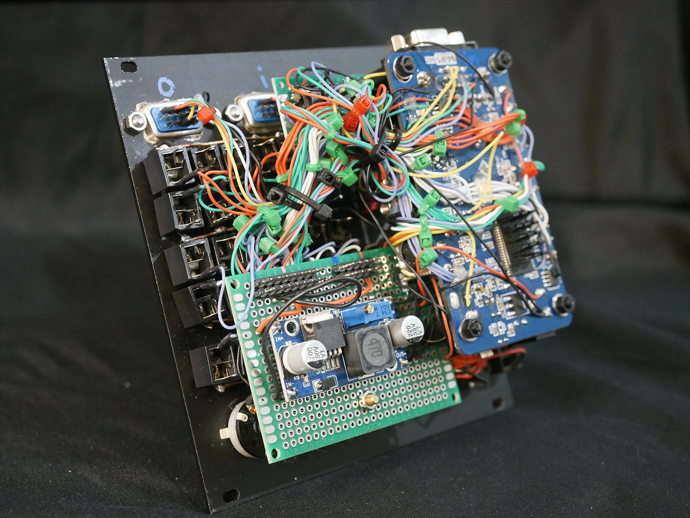
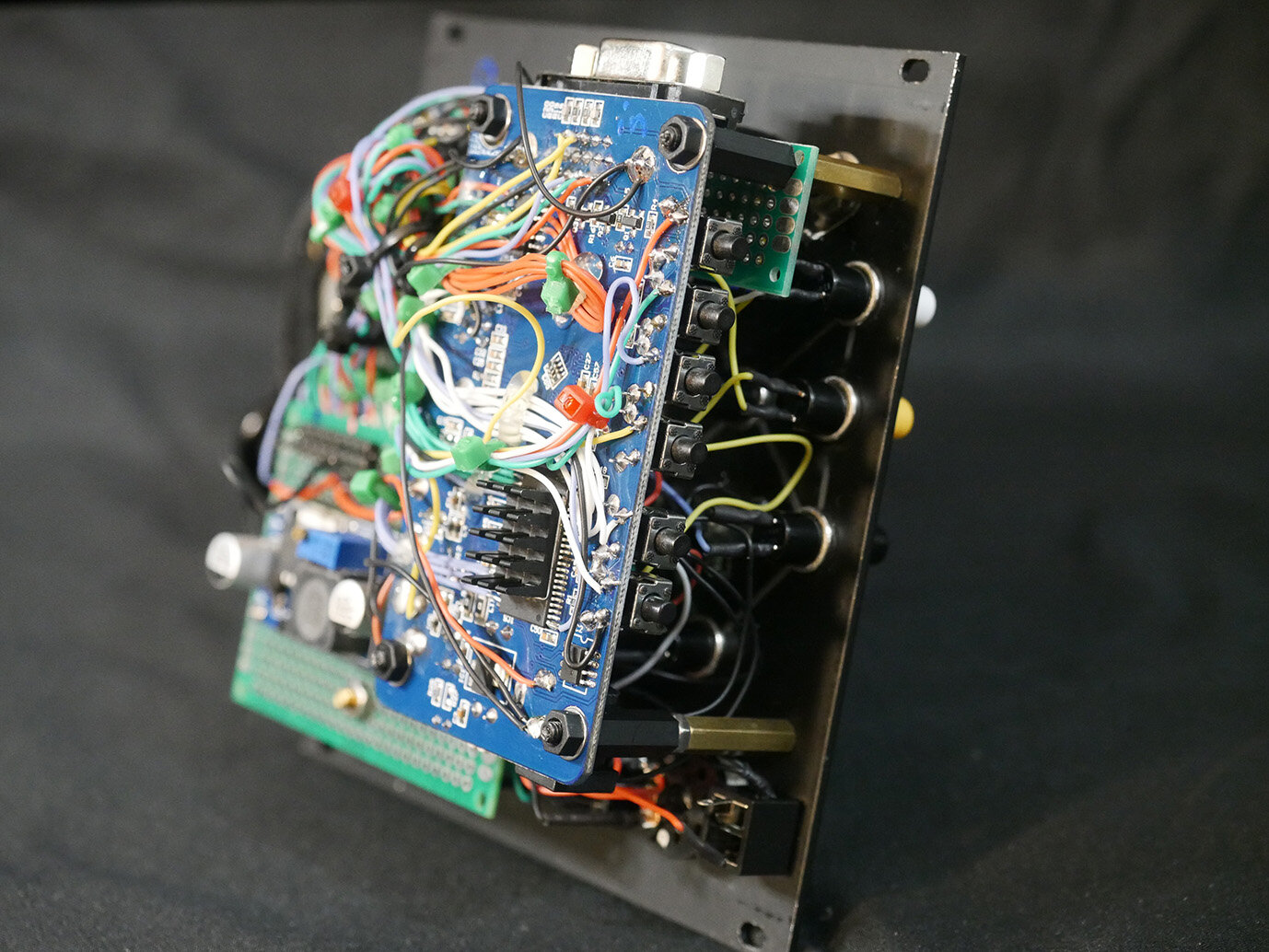
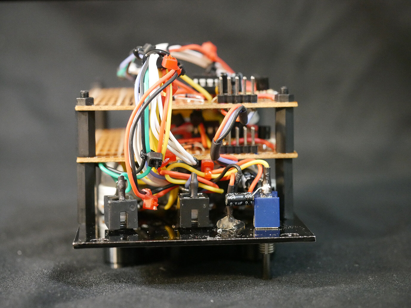
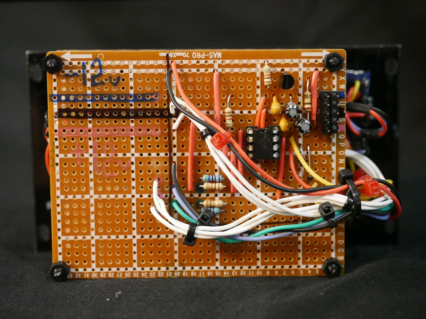
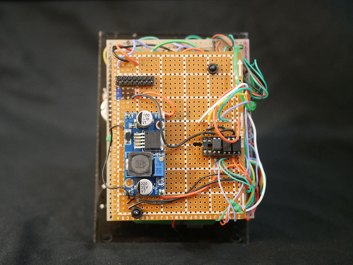
Everything is currently housed in a TipTop Mantis. Most of these modules run on 5v power, but there isn't enough juice on the 5v rail. The original solution was sending 12v through a 7805 circuit for each module, but I ended up building the power for each module around small variable voltage buck converters. Feed 'em power from the 12v rail and dial in exactly what you need - no issues with them so far!